Cut a hole in knee mill column?

wrenchguyrich

Registered
Registered
Joined
Apr 3, 2021
Messages
18
I have a Select 1/2V 7 x 30. Picked up a 3ph 1 hp motor for 42.00, so VFD was the next step.
Works great. The question is where to mount the vfd. In looking at similar units, I see HF, Griz and Jet
models often have a hole in the back of the column where the electrics and/or vfd are installed.
Convenient for sure. Would I be crazy to cut a similar hole in the back of my column about 7" x 10" to
house all my electrics? How about rigidity issues? I would bolt on a 3/16 thick cover on if I thought it
would redeem some lost rigidity. I'm worried about chips in the vfd vents, and I dont want to mount
my electrics on the wall or a great big metal enclosure on the side/back of mill.
I plan to put a control box in front somewhere for speed pot, fwd/rvs switch, estop, etc,
so access to vfd doesn't matter. Your thoughts please.
 
Just mount it to the column or an arm that holds it out the side if you need access to it. Easier and no effect on the rigidity of the column.
 
I realize that you said you don’t want the VFD on the wall but would definitely not cut into the column.

I have a rounded column mill and I just put the VFD on the wall behind the mill.
The low voltage controls are run to a box attached to the left side of the mill.
712deb0adb55d181d10428039a502050.jpg

bd77779db525dfac641946bef4c8ca34.jpg
 
Last edited:
I agree with the others, just mount it on the back of the column. If needed, add a sheet metal shield over the top, spaced a couple inches above the top. That will keep the chips out of the works. You could even mount it in an open front box on the back of the column, just make the box sized for a couple inches clearance all around.
 
Yeah don't hack up the mill, rigidity is king don't be giving it away for some cosmetic purpose. Do it some other way. Your mill will thank you.
-Mark
 
My mill does have a factory access hole in the column, BUT that hole has a very thick rim cast into the column to carry the stresses around the hole. If you just cut a hole it will make the column significantly weaker. I would not do it.
 
Even if you didn't notice any immediate effects on surface finish or increased chatter, you might cause small cracks around the cut area- Hobby grade machines use cast iron that is usually not top quality and may have impurities and inclusions
-M
 
You could mount the VFD in a small breaker box or similar electrical enclosure then mount the box on the mill, this would only require a few tapped holes.
 
I mounted the DRO thru the existing hole in the side of my PM835S knee mill. See https://www.hobby-machinist.com/threads/converting-a-knee-mill-to-3phase-vfd.87352/

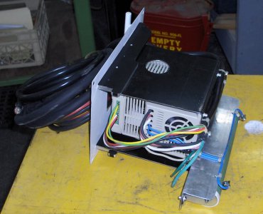
The DRO and braking resistor are mounted to a frame attached to the rear face of the original cover plate. There are two photos of the installation in the thread. Here's an additional photo. @Flyinfool noted that the casting is pretty thick in this area. Note the "hooks" in the bottom surface of the (black anodized aluminum) frame. These allow me to rest the weight of the DRO on the bottom lip of the hole, then swing the DRO frame vertical and insert the cover screws.

I did this installation in October of last year, and it's worked very well. NO problems, well protected from chips, and the large open volume inside the casting allows plenty of ventilation/cooling.
kHPIM0227.jpg
 
Back
Top