Cutting splines questions

Suzuki4evr

Registered
Registered
Joined
Sep 29, 2017
Messages
2,253
Hi guys.
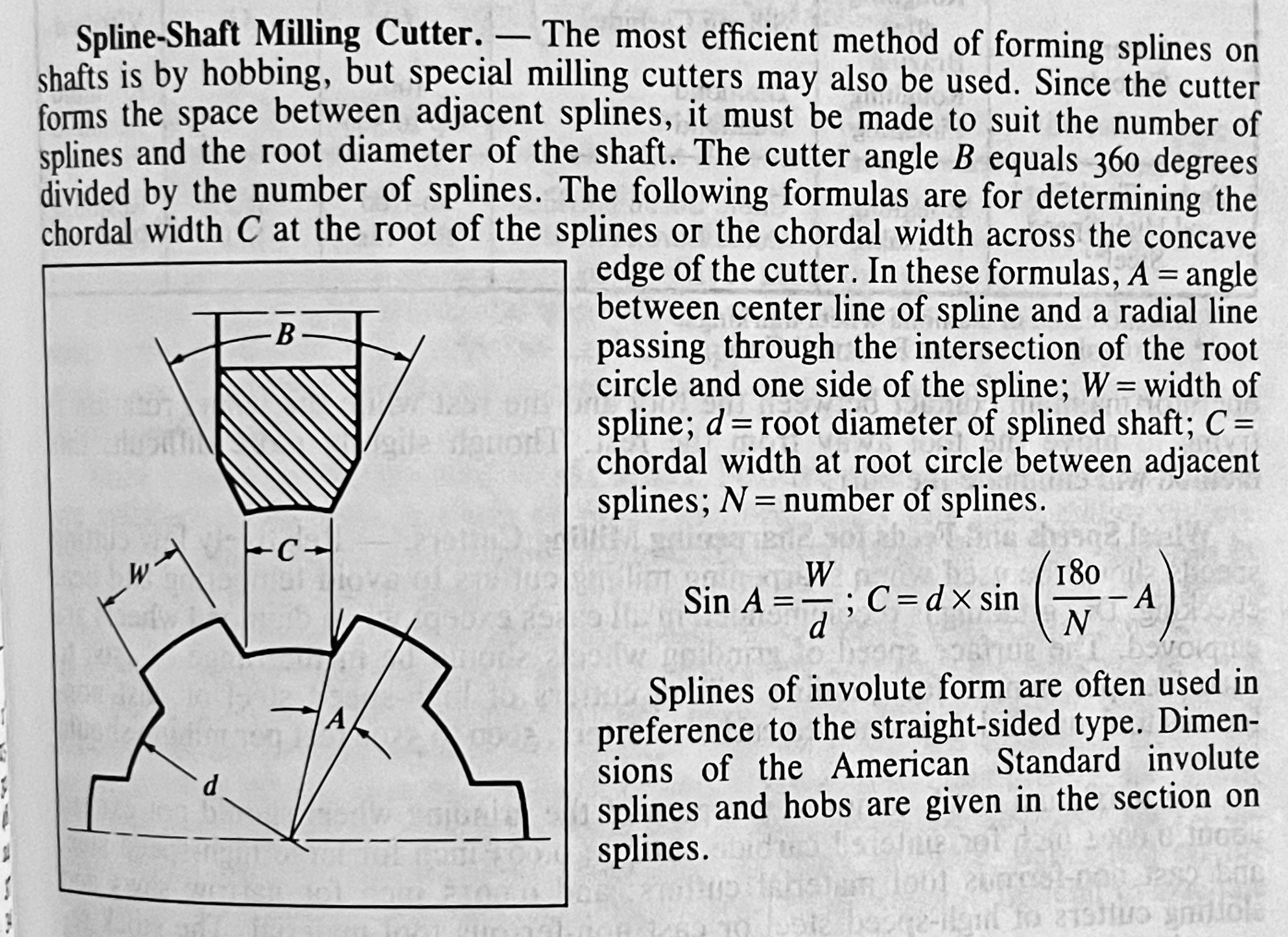
Gears I've made,but now I must machine splines on a shaft for a hydraulic pump. #1.Do you need a spline cutter like a gear cutter?
#2. Or can you make a single point HSS cuuter.
#3.How do you calculate the angle of the spline
#4. How do you calculate depth of cut,does it work the same as gears?
20210416_094617.jpg20210416_094516.jpg20210416_094332.jpg20210416_094251.jpg20210416_094227.jpg20210416_094218.jpg
The angle looks about 45degr.
 
I have to admit to eyeballing it... Worked out great!

 
I have not done it but these are typically cut with a special cutter and a dividing head.
There are at least 2 types of forms: involute and straight.
From the looks yours appears to be involute and would require a special cutter to do properly.

EDIT: TOT has a video on doing straight splines, here:
 
Last edited:
If I did it now, I'd do on the mill with rotary table and quill as Joe Pie often does. But I didn't have a mill back then!
 
Hi Michael,

My only spline project was posted here:
https://www.hobby-machinist.com/threads/my-first-and-second-attempt-at-cutting-splines.83187/

#1.Do you need a spline cutter like a gear cutter?
#2. Or can you make a single point HSS cuuter.
#3.How do you calculate the angle of the spline
#4. How do you calculate depth of cut,does it work the same as gears?

I was lucky, I had printed specs. on the spline I was cutting.
(That meant I could look up a number of things in the Machinery's Handbook.)
Mine required a square 90 degree cutter, and I had one already.

I would think that a single point HSS cutter would work fine....I have seen that method used for gears and it worked there.
Just note that the cutter shape may change with spline size, just as in gears.
If you are copying a spline in the exact same size, then you should be able to grind the cutter to fit the existing one.

As for depth of cut I used the formulas in the Machinery's Handbook to calculate i) what gauge pins to use, and ii) the measurement over those gauge-pins. Obviously, this method requires two gauge pins of the required size, and an "even number" spline in order to have the gauge pins sit 180 degrees from each-other.

I hope you keep posting about your project.
It would help us all improve!

Thanks,
-brino

EDIT: the one thing that I should emphasize from my thread above was just how useful an aluminum test part was _before_ doing the real part.
 
Last edited:
I have cut them on the vertical mill with a dividing head and a single HSS cutter on the side. Looks like you have a good sample to work from. The spline closest to the shaft should have no wear and give you a good reference to fit your tool and measure depth. Depending on the tolerance you need that may work if you can’t find the cutter or get one in time.
 
Wait, are you trying to cut a new shaft, or internal splines in the gears to fit that shaft?
 
It seems that splines commonly have an involute form and Machinery’s Handbook has 20 pages on the imperial involute splines. It also has this on milling cutters:
7e01f48d76976cf4af1950c3b3b579ef.jpg
 
Did an internship in a gear/spline shop. Gives me the right to say I know absolutely jack s*** about gear and spline cutting lol.

Splines are typically parallel sided (as shown in the MH except above) or involute (what I am guessing yours are).

Both types are production cut with hobs on a gear hobber or with milling cutters in lesser production runs.

The involute spline *should* be able to be cut using the standard involute gear milling cutters. Trick is identifying the specification to which the original spline was cut. Critical parameters are imperial/metric, Diametral Pitch/Module, pressure angle, and pitch diameter (measurement over wires). There are also lots of modifications to the standard profile such as truncated addendum/dedendum, flat/radius root, truncated crest, corner chamfers, etc.

A parallel sided spline can be cut using a parallel spline milling cutter (again shown in the MH except above) or approximated using endmills and an indexing head.

If you were able to determine the diametral pitch/module (can be calculated from the number of teeth and the size of the shaft) and the pressure angle (trickier, typically 30 degrees) then you can match the cut using measurements over thread wires stuck in the teeth. Even numbered teeth on the shaft are easy, odd numbered needs a bit of trig to calculate the PD.
 
Last edited:
Looking closely at the end of the splines, where the diameter of the shaft increases not the end of the shaft, I would say that is a straight trapezoidal cut. But I'm certainly just going by what I see ...
 
Back
Top