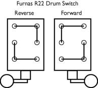
Drum switch, I give up !!!

JPigg55

Active User
H-M Supporter Gold Member
Joined
Nov 8, 2012
Messages
783
Got my new motor from Grizzly, here's the wiring diagram.
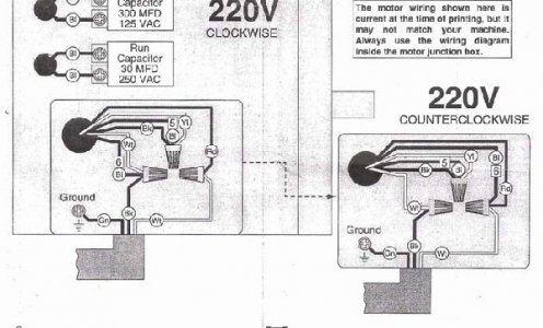
Mill Grizzly G2532 motor0007.jpg
I wired and connected the motor as shown and it works like it's supposed to.
The motor has a 4 place terminal strip in the connection box. I connected the Yellow, Black, & Blue5 wires together on one terminal. I then connected the other 3 wires (Red, White, & Blue6) to their own strip connection.
Now for the drum switch. Here's a picture showing the way it operates (the fwd & rev are switched on mine).
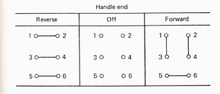
drum sw operation.jpg
I've tried every connection combination I could think of and then some, but cannot figure one out that switches the Blue6 wire from one lead to the other. I had success once, but then I didn't have connection from power to one of the other two leads (White/Red).
I was almost to the point of disassembling the switch to see if I could change the operation to this style (adding a picture of the switch itself.
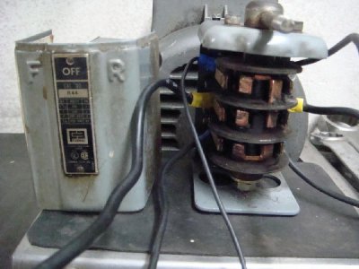
Drum switch.jpgswitch.jpg

Can anyone tell me if there's a way to wire this switch for 220v single phase or if it's possible to dismantle the swich and rearrange the connectors to operate like the R22 switch ???

Mill Grizzly G2532 motor0007.jpg drum sw operation.jpg Drum switch.jpg switch.jpg
 
I have the same Furnas switch on my Clausing 8520, which was supposedly wired for 220V single phase when I got it. Upon closer inspection, some of the wires were disconnected, and it was obvious that it might not run that way. I did manage to figure out from the nameplate on the motor though how to get it to work on 110V and wired it as such, and it worked just fine the very first try. Now I never did try to get it working on 220V, but I did keep a simple drawing of what wiring I had when I got it, and I am including it here as a pdf document. Keep in mind, I do not know if this was correct wiring or not, and I am providing this only as a guide that might help point you in the right direction. Please do not follow the wire colors, or wire yours exactly like this and try it out. The way things are wired at the switch is the part that might help you.

I do not profess to be an electrician of any sort!
 

Attachments

  • MillOldWiring.pdf
    6.7 KB · Views: 51
Thanks for the info.
I'll try again, but I think I tried wiring it this way and it worked except it didn't reverse rotation.
Like I said, I'll try it again and see.
Thanks again.
 
To reverse a single phase motor that uses both a start and run winding, you need to reverse the polarity in only one set of windings in relation to the other. Usually motors that are made for single direction have the run and start windings conected within the windings. You may need to break into the windings and bring the ends out to the terminal strip. From there you can then use your drum switch to reverse the polarity of only 1 winding to make it run fwd and rev.
You should end up with 5 wires entering the motor. 1 active & 1 neutral for the run winding, 1 active & 1 neutral for the start winding, and the earth/ground.
Get a multimeter and check your drum switch. One set of contacts will switch the same way regardless of which way you turn the switch, and another set of contacts will swap as you go between fwd and rev.

Cheers Phil

I realize this, but here's what I've found. Per the motor wiring diagram (see below), all the connections remain the same for both FWD & REV except for the Blue6 lead.
I tried a wiring scheme that worked with the drum switch that reversed the incoming power leads and the motor ran fine, but didn't reverse (no way to swap the Blue6 lead). What I can't figure out is a wiring scheme that will swap the Blue6 connection from one incoming lead to the other which would reverse the rotation.
This might be possible with more wires, but would require a larger cable that wouldn't fit into the motor connection box (hole even too small for a 1/2" penetration clamp).
If all else fails, I plan on just replacing the drum switch with one that has the R22 connection scheme (see below). That would make thinks very easy.
 
Eureka, I got it !!!!
I had to connect one of the motor side power leads on the hot side of the switch with one of the line feed wires, but works just great now.
Thanks everyone for all the help/advice.
 
Eureka, I got it !!!!
I had to connect one of the motor side power leads on the hot side of the switch with one of the line feed wires, but works just great now.
Thanks everyone for all the help/advice.
Awesome, glad you figured it out. I'm pretty good at figuring these things out, in person, with a volt meter and some patience, but online, it's almost impossible for me to explain it. I've been watching this thread, but i had no valuable input....I'm glad you figured it out
 
I realize this, but here's what I've found. Per the motor wiring diagram (see below), all the connections remain the same for both FWD & REV except for the Blue6 lead.
I tried a wiring scheme that worked with the drum switch that reversed the incoming power leads and the motor ran fine, but didn't reverse (no way to swap the Blue6 lead). What I can't figure out is a wiring scheme that will swap the Blue6 connection from one incoming lead to the other which would reverse the rotation.
This might be possible with more wires, but would require a larger cable that wouldn't fit into the motor connection box (hole even too small for a 1/2" penetration clamp).
If all else fails, I plan on just replacing the drum switch with one that has the R22 connection scheme (see below). That would make thinks very easy.
Eureka, I got it !!!!
I had to connect one of the motor side power leads on the hot side of the switch with one of the line feed wires, but works just great now.
Thanks everyone for all the help/advice.
Would you have a drawing how you wired it to work?
 
Maybe you could start a new thread showing your electrical hardware? That thread is pretty old
Easier to start from scratch
 
Last edited:
Yep, here's the drawing.
 

Attachments

  • Switch motor wiring.pdf
    73.1 KB · Views: 4
Back
Top