-
Welcome back Guest! Did you know you can mentor other members here at H-M? If not, please check out our Relaunch of Hobby Machinist Mentoring Program!
You are using an out of date browser. It may not display this or other websites correctly.
You should upgrade or use an alternative browser.
You should upgrade or use an alternative browser.
Edwards Radial 5 build thread --- PHOTOS!
- Thread starter JRaut
- Start date
Superb work.Making progress
- Joined
- Jun 8, 2021
- Messages
- 5
Stunning, inspirational work!! How much machining experience did you have before you started this project? I noticed in an earlier post you said you were a bit new to the hobby. So am I, and you are inspiring me to get out there and fire up the Myford and the mill.
- Joined
- Mar 9, 2018
- Messages
- 465
Thanks for the kind words, @Snider577 !Stunning, inspirational work!! How much machining experience did you have before you started this project? I noticed in an earlier post you said you were a bit new to the hobby. So am I, and you are inspiring me to get out there and fire up the Myford and the mill.
I've had a lathe for about 4 years, and a mill for only about 2-3 years. I did have a milling attachment for my lathe, so I was able to knock out some relatively small projects early on, but this Edwards Radial 5 is basically my first BIG project.
- Joined
- Mar 9, 2018
- Messages
- 465
Episode 29 || Intake and Exhaust Runners and Flanges
Alright, there will be two posts here in rapid succession. And a fair warning --- I didn’t take very many photos for either of these ‘episodes’. I’m frankly running out of steam a bit with the whole writeup thing, so have mostly been focusing on trying to get the job done.
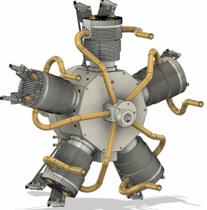
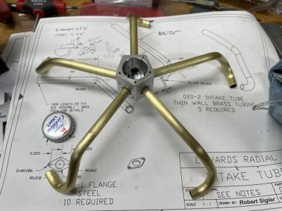
I modeled up the intake and exhaust runners in Fusion mostly for the purpose of designing a motor stand that would avoid everything. But it sure does make a nice visual. I didn’t bother modeling the flanges.
I started with the intake runners. It took lots of trial and error to get the bends correct. The process that worked best for me was as follows:
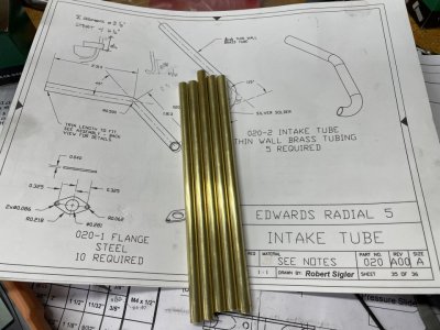
1. Cut some brass tube to length. The tubes are 9/32” diameter with 1/64” wall thickness (1/4” ID).
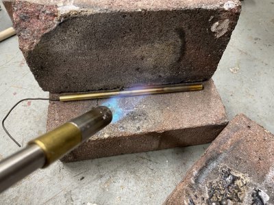
2. Heat to cherry red and allow to cool to fully anneal (the tubes cracked when bending if I didn’t do this)
3. Clean up the ugly surface with some emery cloth.
4. Pack the tube tightly with sand. The playground sand from my backyard turned out to be a bit too coarse, so I made a makeshift sieve to reduce the maximum particle size.
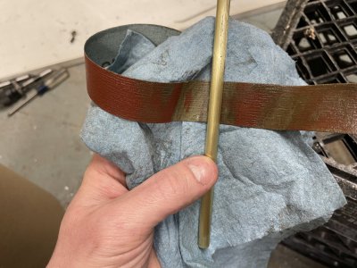
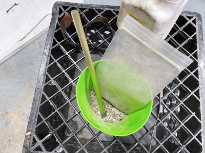
5. Load it up in my newly made Hemingway Kits Tube Bender. I purchased and made the kit specifically for this job. I still need to make a bunch more mandrels for other tube sizes; I’ll probably only make those when the need arises. I used a bend diameter of 2D, which was a bit too tight, even with sand packed into the tube. The drawings called for a bend diameter of about 1.75D, which would have been way too tight; I suspect 2.5D would have been about right.
6. I used a protractor to get the total bend angles correct. (Or correct enough, anyway.)
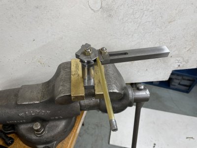
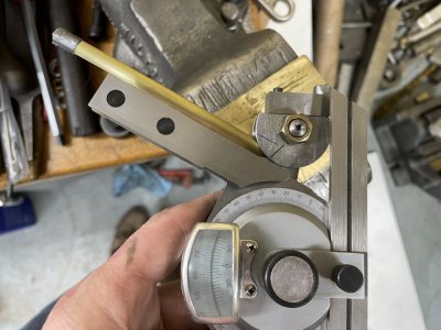
Rinse and repeat until I made all 5 intake runners. The process was similar for the 5 exhaust runners.
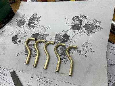
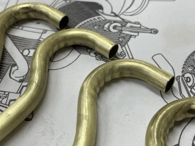
You can see from the little crinkles that the bend diameter was a bit too tight. I’m not worried about it.
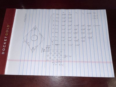
The drawings call for the flanges to be made of steel. I decided to CNC machine them out of 0.04”-thick brass instead. Here’s the ‘program’ I wrote for my ancient Bridgeport EZTrak.
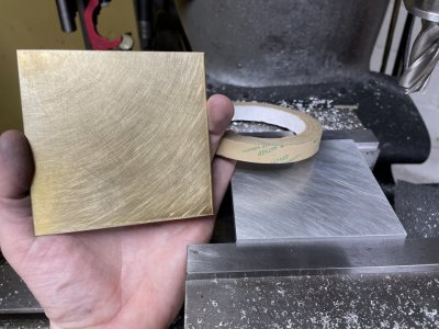
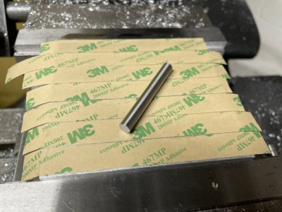
I took a page out of Robin Renzetti’s playbook and used 3M 467MP adhesive for holding the brass sheets to a sacrificial block of aluminum. I used a gage pin to burnish the adhesive down before removing the backing.
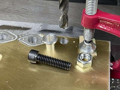
I was nervous that the tape wouldn’t be enough to hold each of the flanges during machining. So I made up a little bushing and bolted each flange down after drilling out the center hole. Then let the CNC do it’s thing x15 plus a few extra.
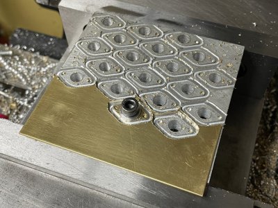
A quick debur and a swipe of some sandpaper and the flanges were done.
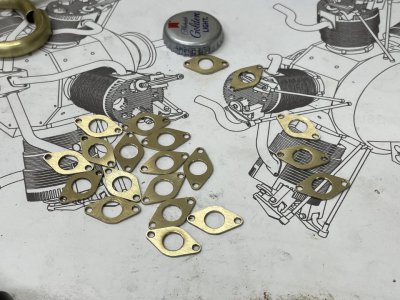
Then I just silver soldered each of the flanges to the intake/exhaust runners while installed on the engine. Pretty painless.
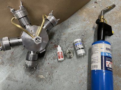
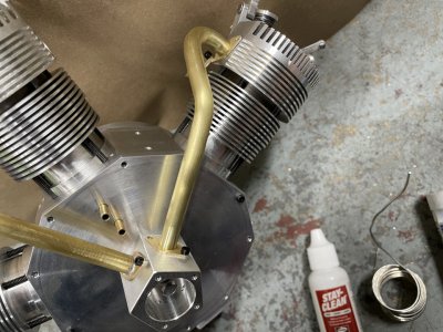
Only mishap is that I accidentally threw too much heat and some of the valve springs while silver soldering, which ruined them. I’ll have a remake about 5 or 6 of them I think.
<EDIT: I also broke off a #2-56 SHCS for the intake runner in one of the heads. Damn. I sure hope I can drill it out, I definitely don't want to be making another head. I'm pretty confident I'll be able to drill it right out with a little carbide PCB endmill.>
And I forgot to get a photo of all the runners complete and installed, but I got some nice photos after I made up the engine stand, which I’ll post probably this evening.
TIME ON INTAKE AND EXHAUST RUNNERS: 19.5 hours
CUMULATIVE TIME: 459 hours
Alright, there will be two posts here in rapid succession. And a fair warning --- I didn’t take very many photos for either of these ‘episodes’. I’m frankly running out of steam a bit with the whole writeup thing, so have mostly been focusing on trying to get the job done.
I modeled up the intake and exhaust runners in Fusion mostly for the purpose of designing a motor stand that would avoid everything. But it sure does make a nice visual. I didn’t bother modeling the flanges.

I started with the intake runners. It took lots of trial and error to get the bends correct. The process that worked best for me was as follows:
1. Cut some brass tube to length. The tubes are 9/32” diameter with 1/64” wall thickness (1/4” ID).
2. Heat to cherry red and allow to cool to fully anneal (the tubes cracked when bending if I didn’t do this)


3. Clean up the ugly surface with some emery cloth.
4. Pack the tube tightly with sand. The playground sand from my backyard turned out to be a bit too coarse, so I made a makeshift sieve to reduce the maximum particle size.


5. Load it up in my newly made Hemingway Kits Tube Bender. I purchased and made the kit specifically for this job. I still need to make a bunch more mandrels for other tube sizes; I’ll probably only make those when the need arises. I used a bend diameter of 2D, which was a bit too tight, even with sand packed into the tube. The drawings called for a bend diameter of about 1.75D, which would have been way too tight; I suspect 2.5D would have been about right.
6. I used a protractor to get the total bend angles correct. (Or correct enough, anyway.)


Rinse and repeat until I made all 5 intake runners. The process was similar for the 5 exhaust runners.


You can see from the little crinkles that the bend diameter was a bit too tight. I’m not worried about it.

The drawings call for the flanges to be made of steel. I decided to CNC machine them out of 0.04”-thick brass instead. Here’s the ‘program’ I wrote for my ancient Bridgeport EZTrak.

I took a page out of Robin Renzetti’s playbook and used 3M 467MP adhesive for holding the brass sheets to a sacrificial block of aluminum. I used a gage pin to burnish the adhesive down before removing the backing.


I was nervous that the tape wouldn’t be enough to hold each of the flanges during machining. So I made up a little bushing and bolted each flange down after drilling out the center hole. Then let the CNC do it’s thing x15 plus a few extra.


A quick debur and a swipe of some sandpaper and the flanges were done.

Then I just silver soldered each of the flanges to the intake/exhaust runners while installed on the engine. Pretty painless.


Only mishap is that I accidentally threw too much heat and some of the valve springs while silver soldering, which ruined them. I’ll have a remake about 5 or 6 of them I think.
<EDIT: I also broke off a #2-56 SHCS for the intake runner in one of the heads. Damn. I sure hope I can drill it out, I definitely don't want to be making another head. I'm pretty confident I'll be able to drill it right out with a little carbide PCB endmill.>
And I forgot to get a photo of all the runners complete and installed, but I got some nice photos after I made up the engine stand, which I’ll post probably this evening.
TIME ON INTAKE AND EXHAUST RUNNERS: 19.5 hours
CUMULATIVE TIME: 459 hours
Last edited:


