

-
Welcome back Guest! Did you know you can mentor other members here at H-M? If not, please check out our Relaunch of Hobby Machinist Mentoring Program!
You are using an out of date browser. It may not display this or other websites correctly.
You should upgrade or use an alternative browser.
You should upgrade or use an alternative browser.
Edwards Radial 5 build thread --- PHOTOS!
- Thread starter JRaut
- Start date
The Nikcole tool wont go that deep for sure. Dont hold me to it but I think catalog shows 0.200 'clearance' from shank to insert tip but in reality DOC is more like 0.185". The issue I've found with grinding thin long blades is even a tiny amount of clearance angle on either side necks the thickness down. Hence a thicker vertical section is probably required to make up for rigidity. Maybe a simple block holding a (round jeweler) slitting blade is worth a try although I'm not sure about setup & tooth engagement.
Last edited:
- Joined
- Apr 29, 2019
- Messages
- 2,060
From what you have said it sure sounds like doing the fins on the mill with a saw is the way to go. If your machine has some wear, you might be better off with the X and Y locked down and using a rotary table (New Toy, I mean tools)
If you want to turn it.
For max rigidity ONLY machine the finned area for less part flex while cutting the fins, After the fins are done then you can go back and machine the small dia near the base and do the bore. Or if you want to turn it all at once then use a center while cutting the fins.
Try not going full depth in one shot.
Start each groove with a very short cutter. Then deepen the groove with a longer cutter and finally get to full depth with the shortest cutter that will reach. Do all the grooves to each depth before moving to the next length tool. grind each cutter with side clearance ONLY in the area that will be cut, the rest should be at groove width so that the groove will help support the side loads that are trying to make the tool wander. AND GO VERY SLOW feed with lots of lube and do not let any heat build up in the part or cutting tool of it will bind and gall the fins and bad things will happen.
With the long thin tool it is more apt to try to wander when starting the groove, even less than .001 wander will send the cutter off at an angle.
Last edited:
- Joined
- Mar 9, 2018
- Messages
- 465
Successfully finished off the fins of a cylinder barrel using a slitting saw on the Bridgeport. Super straight and super consistent; pretty much perfect. And heads and shoulders above what I was getting with a parting tool on the lathe.
Though it's messy and a bit slow: 2 passes per slit x 11 slits @ 7.5"/min means almost an hour of cutting time. I'm sure I could crank up the feed or maybe take it all in one pass, but I'd rather not push my luck.
Just need to finish this one up and bang out 4 more. A detailed post on construction of these will follow in a few days once they're all finished and bolted to the crankcase") .
.

Though it's messy and a bit slow: 2 passes per slit x 11 slits @ 7.5"/min means almost an hour of cutting time. I'm sure I could crank up the feed or maybe take it all in one pass, but I'd rather not push my luck.
Just need to finish this one up and bang out 4 more. A detailed post on construction of these will follow in a few days once they're all finished and bolted to the crankcase
.- Joined
- Mar 9, 2018
- Messages
- 465
This is a very good point. I actually started the 2nd cylinder barrel last night, heeding this advise. So don't let the photo above make you think I ignored you.For max rigidity ONLY machine the finned area for less part flex while cutting the fins, After the fins are done then you can go back and machine the small dia near the base and do the bore.
Awesome! I had to do slitting saw treatment on my heads & yes, slow & messy. I always felt like I was on the verge of folding the blade up into a Pringles chip but steady wins the race. Actually I think this is a good technique to have in the bag for say in-line engines where the cylinder barrels are not round anyways, or like when the cooling fins are interrupted by inlet/outlet ports.
- Joined
- Mar 9, 2018
- Messages
- 465
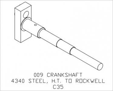
Episode 9 || Crankshaft
Making the crankshaft for my Radial 5 brought me to all corners of my shop: hogging off a bunch of 4140 Pre-Hard on the lathe, turning between centers, dividing head work, mill work, a bit of CNC, some Dremel tool-post grinder work, and some time at the arbor press. This is gonna be a bit of a long one…


The drawings call for using 4340 steel for the crankshaft and heat treating to Rockwell C35. I’ve never really done much heat treatment before and don’t really want to have to send it out to a heat treater. It was quite easy to find annealed 4340 steel that would suit my application, but I couldn’t find any prehard. So instead of going with the drawings, after some research* I opted to go with a chunk of 2”-diameter 4140 prehard with a nominal hardness around C30 instead, which I got off eBay for a reasonable price. Here are some of the data that influenced my choice (I found data other than the plot below, but this is the best I could find showing data for both 4140 and 4340 in one plot). Let me know if you think I’ll regret this choice. I’m second guessing myself a little as I write this post.

Anyway, I slabbed off a 4-5/8”-long chunk of 2”-diameter 4140 prehard, chucked it up in my lathe, faced off the end, and put a center in there.


I had to start with 2” diameter stock because most of the crank web is integral with the shaft portion, the largest diameter of which was about 0.47”. That meant something like 2 or 3 hours’ worth of roughing to get the bulk of the material off. This stuff turns nicely, but is tough and hard, so I could only take about 0.025” DOC per pass without bogging down my 3/4hp single-phase lathe motor. That meant lots and lots of blue chips. ASIDE: I don’t know why everyone complains about long, continuous chips. I love’em. Sure, they take up more space in the trash can but it makes cleanup easy (of course, I could see why a job shop wouldn’t like them).


I roughed it all down to 1/2” diameter and pulled it out of the 4-jaw chuck. Reversed it and held it in a 1/2” collet, put in a center on the other end so I could turn it between centers, and machined it to final length.


I bolted on a lathe dog, blued it up, and marked out the locations of feature transitions. None of these length dimensions are critical so within a few thou is plenty accurate. Then I got to work machining everything to final diameter. I was getting some pretty poor surface finishes (I don’t think my lathe can spin it fast enough?) with my carbide insert tooling, so I left the diameters about a thou heavy and took it down the rest of the way with emery paper, though I did leave the diameters a few tenths larger than the high end of the specification. I can always take a bit of emery paper to fine tune bearing fits later on --- particularly because it’s got centers in both ends. I ground up an HSS threading tool and knocked out the 5/16”-24 thread without a problem. And that was about that for lathe work.


Over to the dividing head to flatten out the web of the crankshaft. Did that between centers as well; easy peasy. Used the same setup to drill/tap a couple holes in the web for bolting on the counterweight, and another hole in the shaft to receive a shear pin.


Then I had to knock out the offset hole in the web to receive a 5/16” dowel pin that acts as a crankpin for the master rod. This was a bit of a tricky setup. I had to make sure I was perfectly parallel to the crankshaft (in two directions), and at the correct offset. The setup would have been a little bit easier if I had a 5C or ER collet block, but the best I could come up with was clamping an MT2 ER collet chuck by a couple flats on the body. Not ideal, but it worked. Drilled and reamed it to spec.


I also did a little bit of CNC action in the setup described above to make the 10-thou shoulder around the crankpin. Okay, bulk of the crankshaft done!


Alright, next component to be made was the counterweight that bolts up to the web. Simple part made from 1018 CR. I rounded the sides with the basic CNC capabilities available to me on my Bridgeport, but this is all noncritical, so could be done with a saw and a file, or a million other ways. Not pictured is an adjustable parallel on the other side of the vise to balance out the clamping forces.


Once I milled out the slot and drilled and counterbored it, it was ready to be bolted to its buddy. Really nice looking part, if I do say so myself.


Alright, last bit to be made is the 5/16” crankpin. The most logical way I saw to do this was to start with a 5/16” hardened and ground dowel, the one I got is spec’d at Rockwell C60. The problem, of course, is how do you machine in the snap-ring groove into a hardened dowel? Well, I made up a little bracket to mount my Dremel on my tool post to use as a cheap toolpost grinder. Dremel conveniently makes cut-off discs with the correct kerf width.


The only problem I encountered while ‘toolpost grinding’ is that the Dremel wheel wore away quite quickly. So I couldn’t rely on my cross-feed dial for determining depth of cut. Easy solution: I just checked with an actual snap ring every once in a while until I got a fit I liked. Then I cut off the dowel pin to length using the same process. And BINGO, perfect.


Last step was to press the pin into the reamed hole of my crankshaft. I had nominal interference fit of 0.002”; see this other thread for a bit of a longer discussion on that topic. It took much more effort on my 3-ton arbor press than it took in my test go. I don’t know why. But I had to really crank on it with everything I had, and bang and bounce it home a bunch of times to get it all the way seated. That pin is never coming out.


Lots of fun to make this crankshaft, and it turned out great! Only thing that remains is to take a little emery cloth to the bearing surfaces during final bearing fitment.


……That is…unless someone convinces me to scrap it and use 4340 instead…….
Next installment on making the cylinder barrels may be a while. I'm mostly finished with two of them but am waiting on some more material to make the rest.
TIME ON CRANKSHAFT: 12 hours
CUMULATIVE TIME: 120 hours
*There’s a lot of scatter in the available data regarding strength vs. hardness for 4140 and 4340, and complete data sets seem to be pretty hard to come by, at least from my searches. But best I can tell, the strengths ought to be similar given similar heat treatments, perhaps with 4340 being a little stronger. 4340 ought to be tougher (in a technical engineering sense) across the board. But because the stress concentrations aren’t too bad on the crankshaft, and the loads imparted on the crankshaft will be reasonably smooth (unless I install it in a plane and it crashes), I think that 4140 will have plenty of toughness to prevent cracking or crack propagation.
To be a bit more thorough, I ran some simple calculations. Based on an estimated 6000rpm and an estimated 6hp (which almost certainly won’t be occurring simultaneously, so this is conservative), I calculate a peak shear stress in the crankshaft---at the root of the threads---of about 25ksi; maybe add as much as 50% more if we include factors like stress concentrations, small inertial/impacts, out of balance, etc. The shear yield stress of 4140 prehard is probably no less than about 60ksi, leaving me a good bit of fat in the design. I frankly have no idea what an appropriate factor of safety is for a crankshaft, but 1.6 seems reasonable enough to me. We shall see.
Making the crankshaft for my Radial 5 brought me to all corners of my shop: hogging off a bunch of 4140 Pre-Hard on the lathe, turning between centers, dividing head work, mill work, a bit of CNC, some Dremel tool-post grinder work, and some time at the arbor press. This is gonna be a bit of a long one…
The drawings call for using 4340 steel for the crankshaft and heat treating to Rockwell C35. I’ve never really done much heat treatment before and don’t really want to have to send it out to a heat treater. It was quite easy to find annealed 4340 steel that would suit my application, but I couldn’t find any prehard. So instead of going with the drawings, after some research* I opted to go with a chunk of 2”-diameter 4140 prehard with a nominal hardness around C30 instead, which I got off eBay for a reasonable price. Here are some of the data that influenced my choice (I found data other than the plot below, but this is the best I could find showing data for both 4140 and 4340 in one plot). Let me know if you think I’ll regret this choice. I’m second guessing myself a little as I write this post.
Anyway, I slabbed off a 4-5/8”-long chunk of 2”-diameter 4140 prehard, chucked it up in my lathe, faced off the end, and put a center in there.
I had to start with 2” diameter stock because most of the crank web is integral with the shaft portion, the largest diameter of which was about 0.47”. That meant something like 2 or 3 hours’ worth of roughing to get the bulk of the material off. This stuff turns nicely, but is tough and hard, so I could only take about 0.025” DOC per pass without bogging down my 3/4hp single-phase lathe motor. That meant lots and lots of blue chips. ASIDE: I don’t know why everyone complains about long, continuous chips. I love’em. Sure, they take up more space in the trash can but it makes cleanup easy (of course, I could see why a job shop wouldn’t like them).
I roughed it all down to 1/2” diameter and pulled it out of the 4-jaw chuck. Reversed it and held it in a 1/2” collet, put in a center on the other end so I could turn it between centers, and machined it to final length.
I bolted on a lathe dog, blued it up, and marked out the locations of feature transitions. None of these length dimensions are critical so within a few thou is plenty accurate. Then I got to work machining everything to final diameter. I was getting some pretty poor surface finishes (I don’t think my lathe can spin it fast enough?) with my carbide insert tooling, so I left the diameters about a thou heavy and took it down the rest of the way with emery paper, though I did leave the diameters a few tenths larger than the high end of the specification. I can always take a bit of emery paper to fine tune bearing fits later on --- particularly because it’s got centers in both ends. I ground up an HSS threading tool and knocked out the 5/16”-24 thread without a problem. And that was about that for lathe work.
Over to the dividing head to flatten out the web of the crankshaft. Did that between centers as well; easy peasy. Used the same setup to drill/tap a couple holes in the web for bolting on the counterweight, and another hole in the shaft to receive a shear pin.
Then I had to knock out the offset hole in the web to receive a 5/16” dowel pin that acts as a crankpin for the master rod. This was a bit of a tricky setup. I had to make sure I was perfectly parallel to the crankshaft (in two directions), and at the correct offset. The setup would have been a little bit easier if I had a 5C or ER collet block, but the best I could come up with was clamping an MT2 ER collet chuck by a couple flats on the body. Not ideal, but it worked. Drilled and reamed it to spec.
I also did a little bit of CNC action in the setup described above to make the 10-thou shoulder around the crankpin. Okay, bulk of the crankshaft done!
Alright, next component to be made was the counterweight that bolts up to the web. Simple part made from 1018 CR. I rounded the sides with the basic CNC capabilities available to me on my Bridgeport, but this is all noncritical, so could be done with a saw and a file, or a million other ways. Not pictured is an adjustable parallel on the other side of the vise to balance out the clamping forces.
Once I milled out the slot and drilled and counterbored it, it was ready to be bolted to its buddy. Really nice looking part, if I do say so myself.
Alright, last bit to be made is the 5/16” crankpin. The most logical way I saw to do this was to start with a 5/16” hardened and ground dowel, the one I got is spec’d at Rockwell C60. The problem, of course, is how do you machine in the snap-ring groove into a hardened dowel? Well, I made up a little bracket to mount my Dremel on my tool post to use as a cheap toolpost grinder. Dremel conveniently makes cut-off discs with the correct kerf width.
The only problem I encountered while ‘toolpost grinding’ is that the Dremel wheel wore away quite quickly. So I couldn’t rely on my cross-feed dial for determining depth of cut. Easy solution: I just checked with an actual snap ring every once in a while until I got a fit I liked. Then I cut off the dowel pin to length using the same process. And BINGO, perfect.
Last step was to press the pin into the reamed hole of my crankshaft. I had nominal interference fit of 0.002”; see this other thread for a bit of a longer discussion on that topic. It took much more effort on my 3-ton arbor press than it took in my test go. I don’t know why. But I had to really crank on it with everything I had, and bang and bounce it home a bunch of times to get it all the way seated. That pin is never coming out.
Lots of fun to make this crankshaft, and it turned out great! Only thing that remains is to take a little emery cloth to the bearing surfaces during final bearing fitment.
……That is…unless someone convinces me to scrap it and use 4340 instead…….
Next installment on making the cylinder barrels may be a while. I'm mostly finished with two of them but am waiting on some more material to make the rest.
TIME ON CRANKSHAFT: 12 hours
CUMULATIVE TIME: 120 hours
*There’s a lot of scatter in the available data regarding strength vs. hardness for 4140 and 4340, and complete data sets seem to be pretty hard to come by, at least from my searches. But best I can tell, the strengths ought to be similar given similar heat treatments, perhaps with 4340 being a little stronger. 4340 ought to be tougher (in a technical engineering sense) across the board. But because the stress concentrations aren’t too bad on the crankshaft, and the loads imparted on the crankshaft will be reasonably smooth (unless I install it in a plane and it crashes), I think that 4140 will have plenty of toughness to prevent cracking or crack propagation.
To be a bit more thorough, I ran some simple calculations. Based on an estimated 6000rpm and an estimated 6hp (which almost certainly won’t be occurring simultaneously, so this is conservative), I calculate a peak shear stress in the crankshaft---at the root of the threads---of about 25ksi; maybe add as much as 50% more if we include factors like stress concentrations, small inertial/impacts, out of balance, etc. The shear yield stress of 4140 prehard is probably no less than about 60ksi, leaving me a good bit of fat in the design. I frankly have no idea what an appropriate factor of safety is for a crankshaft, but 1.6 seems reasonable enough to me. We shall see.
Last edited:
- Joined
- Aug 3, 2017
- Messages
- 2,437
I suspect you really will be OK with 4140. Like you said, unless you put this in a plane that expects high hours, I would think even a mild steel would be fine
That said, when turning you likely would have been better off with HSS. I was able to get a fine finish out of 4140HT when I turned.
Also, if I had a lathe that could only take that little in bites, I would have considered making it out of 4 pieces instead of 3, pressing/pinning in the main shaft as well.
I'm not building the Edwards but have the PDF plans. I missed the heat treat detail on the drawing itself. I just saw the material call-out. Do you think its about raising the strength as per your graph or giving hardness on the bearing & journal surfaces?
I used 1144-SP on my radial but its not running so cant offer anything in terms of 'it worked / didn't work'. Too late now! :/ I don't recall off hand if some of the other Edwards builds heat treated theirs, but I rather think not. That in itself doesn't mean anything. I think the Edwards is a solid, well thought out design. It could be other radials circumvented HT with a bit more meat strength wise, or they just aren't run that hard.
I used 1144-SP on my radial but its not running so cant offer anything in terms of 'it worked / didn't work'. Too late now! :/ I don't recall off hand if some of the other Edwards builds heat treated theirs, but I rather think not. That in itself doesn't mean anything. I think the Edwards is a solid, well thought out design. It could be other radials circumvented HT with a bit more meat strength wise, or they just aren't run that hard.
Attachments

- Joined
- Mar 9, 2018
- Messages
- 465
I'm pretty sure they need the strength, more so than the hardness for bearing journals. After all, the components of the roller bearings themselves are doing all the moving. The bearing journals and the internal bearing races aren't supposed to be moving with respect to each other.Do you think its about raising the strength as per your graph or giving hardness on the bearing & journal surfaces?
Dead soft 4340 has a shear yield strength of around 40ksi. My (conservative) calculations puts the peak shear demand around 35ish ksi. It would probably work, but that'd be too close for comfort for me. Heat treating can greatly increase the strength (at the cost of a little bit of toughness and ductility).
Or think about it this way:
They say the Edwards can output about 6hp, which is similar to a lawnmower, pressure washer, snow blower, etc. That sort of equipment usually uses a 5/8" or 3/4" diameter output shaft.
The minimum diameter of the crankshaft at the root of the 5/16-24 thread is only about about 1/4".
Would you want to be running your 6hp lawnmower off a 1/4" shaft??
Granted, I'm conflating things a bit: the Edwards and lawn equipment won't be running at the same RPM; lawn equipment output shafts have threaded portions too; lawn equipment will see more impact loads; some of my assumptions are pretty conservative; and I rather doubt that the Edwards will actually pump out 6hp.But it helps to bring it back to real-world examples to see if things are at least in the right ballpark. Seems to me the crankshaft doesn't have a ton of fat in the design; rightly so as saving weight in an aircraft engine is rather important.