- Joined
- Feb 2, 2013
- Messages
- 3,627
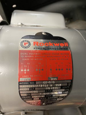
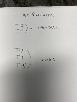
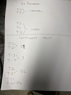
i made a short video on testing the windings on a 5 wire 115v 1/2 hp 1740 rpm General Electric single phase capacitor start motor.
other motors will test very similar
other motors will test very similar