
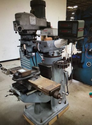
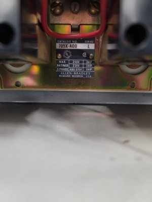
This electircal box was mounted to the back side of my Bridgeport. You can faintly see it sticking out the back. It was wired to the switch. It appears to be a forward/reverse box? If so this would mean you can run the spindle in both direction in high gear? Maybe I'm way off here hoping someone would have some insight.

-
Welcome back Guest! Did you know you can mentor other members here at H-M? If not, please check out our Relaunch of Hobby Machinist Mentoring Program!
You are using an out of date browser. It may not display this or other websites correctly.
You should upgrade or use an alternative browser.
You should upgrade or use an alternative browser.
Electrical box mounted on Bridgeport
- Thread starter S5rx7
- Start date
- Joined
- Nov 23, 2014
- Messages
- 2,609
I can't tell from your pictures but in normal use the BP can go in both directions in both open spindle and back gear. My BP has a HIGH/LOW RANGE power switch on the LH side of the head. Normally this is left in the OFF center position. Flip it up to HIGH RANGE with the head in open spindle (high gear) and the spindle turns clockwise. Flip it to LOW RANGE with the head in open spindle and it turns CCW. It's bass-ackwards when in back gear (low gear). Flip to LOW RANGE while in back gear to turn CW, HIGH RANGE to go CCW.
In summary, match the RANGE to your spindle gearing for CW, mismatch for CCW. I use the LOW RANGE all of the time for power tapping. Turn on the BP (in LOW RANGE), advance the quill until the tap engages, flip the power off to stop the mill, and flip the power back on to HIGH RANGE to retract the tap.
By the way, there are a couple of unique things on my BP. The previous owner made a bell crank for flipping the power switch. The knob is mounted by the kick-out mechanism. Lots more convenient than the high-mounted switch. The toggle switch mounted just above the boring feed rate knob is the ON/OFF switch for a spindle light.
Also, my BP is powered by a static phase converter. The previous owner mounted the converter above the Anilam controller and used a DPDT lamp switch to power up/down the converter. In use, the mill's normal power switch is left in the HIGH/LOW RANGE and the mill is powered on/off with the toggle switch. As cheesy as it looks, it works well for me. I don't understand the electrical side of it, but if I leave the phase converter on and use the normal switch for ON/OFF, the phase converter buzzes with the normal power switch off. I suspect the relay in the static converter is cycling at 60 Hz. I've read others having the same condition with their converters. As usual, more than you wanted to know!
Bruce
- Joined
- Aug 3, 2017
- Messages
- 2,437
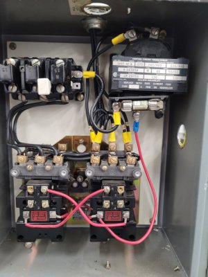
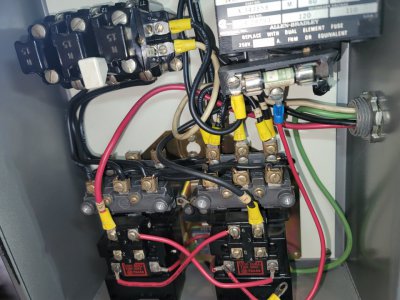
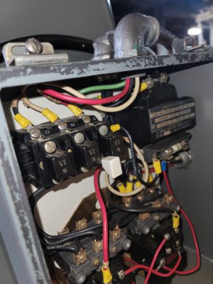
It appears to be a contactor box to me (to be used with a magnetic switch), I don't see anything about 'reverse'. I would imagine there is a drum switch somewhere (either between this and the motor, or between the source and this box) that changes direction.
- Joined
- Dec 14, 2018
- Messages
- 629
Looks like a FOR/REV contactor set up. Some Bridgeport mills, and clones like mine have a drum switch. The reversing is done mechanically within the switch verses having individual for/rev contactors (like in your pic's) that are energized electrically by a switch, which I assume is mounted on the left side of the machine.
- Joined
- Aug 3, 2017
- Messages
- 2,437
Ah, TIL! Listen to him insteadLooks like a FOR/REV contactor set up. Some Bridgeport mills, and clones like mine have a drum switch. The reversing is done mechanically within the switch verses having individual for/rev contactors (like in your pic's) that are energized electrically by a switch, which I assume is mounted on the left side of the machine.
") I saw the two contactors and it looked like my shaper so I figured it was like that!).
I saw the two contactors and it looked like my shaper so I figured it was like that!).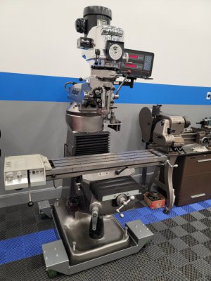
- Joined
- Feb 8, 2014
- Messages
- 11,144
The reversing contactor was most likely installed to move the high motor voltage away from the drum switch to meet a regulatory requirement. Normally 240V or even 480V is wired directly to the drum switch, and that is not the safest way to do it. Much safer for the operator with the reversing contactors and the drum switch switching 120V.
Today, running the motor with a VFD and having 24VDC controls would be my first choice.
Today, running the motor with a VFD and having 24VDC controls would be my first choice.