Electrical Guru’s Here here!

HuD_91gt

Registered
Registered
Joined
Oct 25, 2020
Messages
44
Hello everyone,

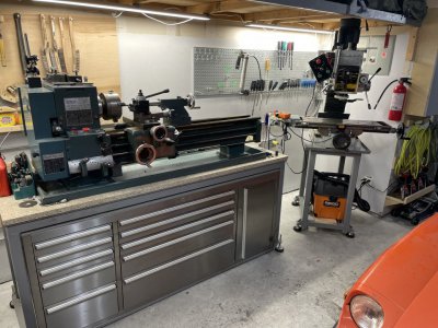
I recently purchased an RF45 clone ZAY7945FG/1 with an electrical issue.

I will start off, I am no guru with AC electrical, but am fairly competent when it comes to DC systems. I figured I should be able to troubleshoot this.

So the machine is wired for 240v, and when the electrical contractors are pressed the motor runs as it should (both forward and reverse).

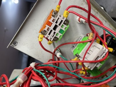
I’ve tried following the voltage from the outlet into the machine, and it seems to disappear at the CU-11 Contactors (a form of relay I assume?)

There is 23v pretty much everywhere where 120v is not seen (using one side of voltmeter grounded).

I tested continuity at the 3 safety switch I found (protection shield, then two on the quill). They seem to work fine while measuring 23v.

I have no wiring diagram for this exact machine.

transformer shows proper voltage at input and output is also 23v.

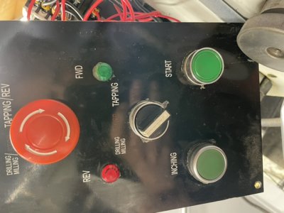
There is no sign of 120v in the electrical “button panel (emergency stop etc).” 23v again.

The 2amp ceramic fuse checks out.

Any input is greatly appreciated.

E685B1CF-756B-4F75-829F-E86A4D24499D.jpeg
 
Last edited:
Here it is next to my import mill.
 

Attachments

  • C5145EDF-C6D1-4619-8932-F731B85AFABA.jpeg
    C5145EDF-C6D1-4619-8932-F731B85AFABA.jpeg
    167.7 KB · Views: 106
The contactors are a type of relay. They are normally open and close when they are turned on. Quite often there is a "sealing contact" on the motor contactor. That closes when the start button is pressed and the contactor pulls in. That is wired in parallel with the start button which is why the start button does not have to be held forever because the auxiliary contact of the contactor "seals" the circuit. The stop button is normally closed (has continuity) when NOT pressed and opens when pressed. When working right, the stop button breaks the circuit, the contactor drops out and the start button will need to be pressed again to start things again. That is, if all is working. From your photo, the top contactor with the over-load unit to the left appears to be your motor contactor.

Don't forget, there's high voltage in there that can bite you so be careful.

Please confirm that you have a start button, a stop button and an emergency off (EMO) button type circuit. Is the emergency off button a momentary one or one you have to twist and pull outward to reset? If it is one that has to be reset, do that first. Is there 23 VAC on both sides of the EMO after it is reset?

If that is not it, I would try this:

Look for the 23 VAC on both sides of the start button contacts. It should be always present on one side and only present after the button is pressed on the other side. Pressing the start button should start it again...

Read the contactor coil ratings. Are they the proper coils? Did they put a 220VAC coil in the contactors by mistake?

Try this and get back to us.
 
This is a classic motor start/stop circuit. It is probably not too unlike what you have there. The EMO would likely be between the fuse and the stop button contacts. The "M" is the contactor coil and aux contact. There may or may not be other normally closed contacts in the circuit that are in series with the stop button or in series with the "M" coil. These circuits can vary. For example, this one has two stop and two start buttons. Ignore the extra buttons in this circuit. The OL (over-load) senses motor current and will open if the motor is overloaded for too long. There is a reset button right on top of it. Come to think of it, try resetting the "OL" using the button on the OL.

1641762288785.png
 
How the above works:

Starting out, if the OL has been reset (closed), the motor is in the off condition and the EMO is reset, there is voltage (24VAC) provided to the stop button's left contact. Because the stop button is normally closed, voltage is present at the right-hand side of the off button contact. Once someone presses the "Start" button, current can flow to the (M) contactor coil and then the M contactor is powered and it's auxiliary contact closes. Once the aux contact -| |- "M" closes, that "seals" the current flow around the start button -|\|- and is the reason that you don't have to hold the start button forever. To stop the motor, a stop button is pressed, interrupting the current to the (M) coil which puts things back to the original state, ready to start over.

If the motor is overloaded, the "OL" opens up which keeps the motor contactor from being turned on until it is reset.
 
Last edited:
Wow. What an amazingly quick reply. I am going to go over your post with a fine tooth comb after I finish making lunch. I quickly went down and tested the emergency stop switch. It is of the twist and pull type.

It has 23v coming into both sides (3) of the switch, then alternates between the two on the other side(5 and 17) pending the position of the switch. Unless wired incorrectly I’d say the switch is working correctly.
 

Attachments

  • 85447EA5-7DF1-4F1C-9C52-C8DDF7B7D518.jpeg
    85447EA5-7DF1-4F1C-9C52-C8DDF7B7D518.jpeg
    110.6 KB · Views: 103
  • 87CF48ED-FE26-4066-B719-30A4004C6F83.jpeg
    87CF48ED-FE26-4066-B719-30A4004C6F83.jpeg
    82.3 KB · Views: 103
Agree with Reddinr, also: You don't want to be referencing your meter from ground on the 24 volt side of the transformer. You should have one meter lead on one side of the transformer 24 volt output and use the other meter lead to probe around the 24 volt path. The 24 volt system may or may not have one side of the 24 volt supply tied to ground by the factory- best to assume it is not- it can give confusing readings
-Mark
 
Last edited:
Hard to tell for sure from the photo but it looks like wire 2 ties the transformer to ground. Easy to check on site. Still, Mark has good advice, best to be sure.

I have to step out for a few hours. Will try to check back in this evening. Good luck.
 
Ok. I’ll posted a little bit at a time as I work my way through this.

Thank you both for your help.

The start button shows 24v on one side. Once activated, 24v shows on both sides. Then the “off” selector is switched to off. The one side of the start switch goes back.

so it seems to allow the voltage to go through as you describe, and hold it close until the power is interrupted.


How do I reference the 24v system if I should be using ground?

I can’t find a O/L switch in this motor. I do see some sort of load protector in the control box (with the red and dark blue buttons). I did reset that. More of a theory question about the O/L…. If it’s tripped, would the motor still run when I press the contactors?
 
The O/L should be the top, left item in your first photo. It is connected mechanically/electrically to the top contactor. If it is tripped, the contactor will not close and the motor will not run.

The circuit I sent is too simple. There is forward / reverse and Jog in your box. This diagram may be a little closer but not really that close. (Does anyone have the diagram for an RF45 like this one?) I couldn't find a better one in a short time looking. The story here is that a JOG button only closes one of the contactors for as long as you hold it in. It is like a start button without a sealing contact. Only one of the contactors should turn on at one time. One is for forward and the other for reverse. I'm guessing that is what you have there.

Check to see if there is a wire from one side of the 24 VAC to ground. If so, you can use ground as the reference. If not, use the low voltage terminal on the transformer that show a voltage when you measure between your EMO and the terminal. The other terminal (not the common terminal) would show ~0 Volts AC.

1641767101130.png
 
Back
Top