Electrical Guru’s Here here!

I would not expect to find any 120VAC in that system. The main power is 240VAC and the control power is 24VAC. In reading your first post it would seem that everything is working normally. If all the functions work as they should, then I think you are OK. The only thing that I would concern myself with is that the machine is properly grounded.
 
Hi Jim.

As stated before. My AC knowledge is lacking. The 120 v reference is seen when the multimeter is connected to the ground “bus bar” of the machine. I am in Canada, so our 240v is built up of 2 120v lines.

when connecting the multimeter between each of the 120v lines from the house, they combine and get the 240v.


Perhaps I’m not quite understanding your comment? The functions of the machine are not working properly. The electrical contactor for the relays needs to be pushed for the motor to be turned on. The buttons on the control panel at this point do nothing.

I’m still having trouble getting an understanding of transformer referencing line.
There is 2 low voltage connections on the transformer when referencing ground and 2 at 120v. Is it possible for someone to dumb down the explanation when referencing the emergency cut off as described above?

it does not look like the transformer is connected to ground at all.
 
I kind of misspoke there, yes, you would see 120V between ground and one of the hot legs. But that 120V is not used in any part of the circuit. That's the way North American power is wired at the pole, each leg is 120V to ground (neutral)

Not sure about the E-stop button. Does it seem to work as expected? Maybe I misunderstood your post.
 
The O/L should be the top, left item in your first photo. It is connected mechanically/electrically to the top contactor. If it is tripped, the contactor will not close and the motor will not run.


Check to see if there is a wire from one side of the 24 VAC to ground. If so, you can use ground as the reference. If not, use the low voltage terminal on the transformer that show a voltage when you measure between your EMO and the terminal. The other terminal (not the common terminal) would show ~0 Volts AC.

View attachment 391532
In regards to the emergency stop I was talking about the comment quoted here. I don’t quite understand it. (Saying that the over load circuit I found is the one described above). It seems fine.

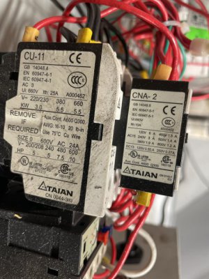
Contactor seem to be labelled correctly?
 

Attachments

  • image.jpg
    image.jpg
    98.9 KB · Views: 85
Last edited:
OK, now I think I understand. If you manually push in a contactor the motor will run?

I can't seem to load the picture, maybe you can repost it.
 
OK, now I think I understand. If you manually push in a contactor the motor will run?

I can't seem to load the picture, maybe you can repost it.
Yes exactly. Manually push the contactor and the motor runs. Manually push the other contactor the motor runs in reverse.
 
Yes exactly. Manually push the contactor and the motor runs. Manually push the other contactor the motor runs in reverse.

OK, that is what I would expect.

Yes, the contactor seems to be labeled correctly.

If nothing works, the first thing I would check is the E-stop switch contacts. About 80% of the time this is the problem.
 
I have gone over the emergency stop button as described previously. It seems to be working correctly.

How do these systems operate? Obviously the motor used 240v. Is the 24v system used to just decrease electrical noise in the control box? What is the point of dropping the voltage.

I’ve gone over the CNA-2 relays. They seem to have continuity. One pole loses continuity when certain switches in the quill are activated. This is obviously to deactivate the forward rotation, then start the reverse rotation.

I mean I haven’t written out a complete diagram for this but everything seems to connect. The only part I don’t understand is what turns the relay to turn the high voltage power to the motors? I assume the big CU-11 looking relay things. They have high voltage going in one side, and just can’t seem to get it going out the other. LOL!
 
Hard to see from your pictures, but it looks like the CU11's are the motor contactors.

Did you disconnect the wires from the red contact block on the E stop button and measure the continuity across those terminals, with an ohm meter, with the E stop button pulled out? The reading should be near 0 ohms.

The 240V is the motor power, the 24V is the control power. It is done this way so there is not 240V across the switches on the machine. It's safer.

What is the red button on the green wiring block in your first picture? Is that the fuse holder?
 
Resistance across the B side of the E stop Button (I assume this is what you mean by red side? It’s orange in my side, vs green on the other side) I get 0.001-0.000ohms. Wires were disconnected.

The red button is the fuse. It tests ok.

thanks for the help with this everyone.
 
Back
Top