
The fuse for the transformer… I only know of the one fuse under that whole panel. It’s listed as a 2amp. I should probably ensure it’s correct.A couple of thoughts.
First, be sure the fuse to the transformer is sized close to the transformer rating. 50 VA would be about 1/4 Amp at 210V. So, no more than maybe 1/2 Amp at most. Do this especially on the first turn-on (Try starting with a 1/4 Amp slow blow) because maybe there is a short circuit that opened the primary coil vaporizing the wire you can't find. The fine wire can get weak due to vibration and can go pfffft before the fuse. Who knows at this point though.
Second, some people have put a cable-connected counter-weight on the Z axis to take some of the weight off.
Here's a fancy brake-rotor-based one that came up when I googled "z axis mill counter weight".
View attachment 391717

-
Welcome back Guest! Did you know you can mentor other members here at H-M? If not, please check out our Relaunch of Hobby Machinist Mentoring Program!
You are using an out of date browser. It may not display this or other websites correctly.
You should upgrade or use an alternative browser.
You should upgrade or use an alternative browser.
Electrical Guru’s Here here!
- Thread starter HuD_91gt
- Start date
- Joined
- Jan 5, 2014
- Messages
- 943
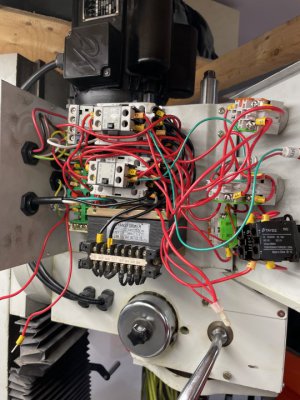
That 2A fuse is likely the one for the transformer, however, it may be on the output of the transformer. Maybe trace some wires to see how it is connected. 2A is probably about right for an output fuse given the size of the contactors you have there. If it is an input fuse it would be a bit large I would think.
- Joined
- Jan 5, 2014
- Messages
- 943
You are probably just fine with only an output fuse. It protects the transformer from overloads and shorts of the low voltage circuitry. The transformer primary kind of protects itself if the transformer shorts out internally. The tiny wire just vaporizes and you're done. Having a primary fuse on the transformer may be very slightly safer for a small transformer like this but I wouldn't worry about it as long as you keep the covers on your control box. If the transformer shorts then it has already gone to meet its maker anyway. A primary fuse might blow but then you need to buy a transformer AND a new primary fuse... It is a different story for larger transformers where you want a primary fuse or breaker to protect input wiring and the transformer.
You stated you had 24 volts on output of start switch when pushed, this indicates transformer good.
Pushing contractors to make motor go proves high voltage good.
Look closely at contractors.
There will be high voltage on all but 2 or 3 wires.
The coil wires are what you need to identify.
Start at your stop switch.
Get a roll of masking tape and a sharpie.
Make tags and number them in pairs, 1a, 1b 2a, 2b and so on.
Sheet of paper to describe your system.
Start and do this.
Place tag 1 at wire on Start switch that is switched output, the one that changes.
On paper note wire 1a switched 24 volts from Start switch.
Carefully follow the wire to where it goes and tag it with the b side and note where it goes.
Check voltage both ends to be sure, should act same at both ends.
If not you lost the wire or wire open.
With both contractors not working you likely have. Ommon problem and not open coil.
When the wire goes to a switch, check it with voltmeter.
If a contactor coil check voltage too but also check other side of coil.
If you get 24 vac on both sides then the ground is not connected.
It could have an interlock that removes ground to prevent operation.
Continue to tag and trace the wires as that is the path the current flows and it must get back to the transformer.
Sent from my SM-G781V using Tapatalk
^^^ I’ll go through this. I’m starting to understand how this works now. Basically a series of relays which eventually lead to the main high voltage contactor.
Easy enough to figure out if I just draw it all out…. But, Before we get to that point.
My old transformer is toast, whether from me, or it was toast already… but I do have the new one now.
It squeezed in with a single tapped screw and fits like a glove (although bigger).
Im having an issue understanding how the output should be wired though. I have a feeling I could wire it either way but just want to be sure.
I tested the transformer resistance Input side was 0.012kOhms, and 0.015 for the 200/220v inputs. I wired for the 220v using the 220v input.
when powered up, I get 23.3 v out the output. I assume this won’t be an issue. If it is, I can probably go down to 200v input and the 22v output to get the voltage im looking for. It’s a guess but maybe. lol.
Now if someone could help me with the other wires. Lol.
The input was easy, as the old transformer used a single input for 240v or 380v, you just move the other wire to your desired input. The output side is more challenging as it uses a completely different set of inputs for each “choice”.
I should also mention I removed the “chip guard” switch completely. I knew it was going to fumble me up if I still had it on there, somehow getting moved to the wrong position. It was easy enough to figure out how to jump the wires. My brain says leave it along until you figure out the other issues, but I had idle time! Lol and I didn’t see the reply above either. Haha but couldn’t start on that until I had a transformer.
Attachments
Last edited:
Transformer should have 4 wires.
2 input and 2 output.
Does not matter which way on either, input goes to line cord via main switch or fuse.
Output goes to everything else.
It is alternating currently polarity does not matter.
After connected plug in, turn on and see what happens.
Confirm your 24 volts at start then continue.
Exact not critical, 22 to 26 will work.
Sent from my SM-G781V using Tapatalk
It Works! That sweet sound of import precision straight cut gears! Thanks so much guys!
I’m honestly still a bit dumbfounded how I could have possibly been getting 24v out the other side, with a botched transformer. But hey. Saw something off and went with it!
I’m honestly still a bit dumbfounded how I could have possibly been getting 24v out the other side, with a botched transformer. But hey. Saw something off and went with it!