ELS Conversion on Weiss 1127

For what it is worth, wiring these GX connectors can be confusing. I reversed the rotation more than once. Had to redo them. Also reading the pin numbers isn't that easy...
 
Yes, that's very possible to test the signal wiring. What do you have for test equipment? Volt ohm meter? Scope? Test lamp? Then I can suggest what to do. Please attach a picture of the stepper driver with all the connected wires right now. Maybe there is something that jumps out. Maybe a picture of the cable ends at the ELS controller without the hoods would be useful as well. Basically both ends of the cable you built.

If you have a volt ohm meter, you could set it to ohms or continuity. You could even open the ELS box and ring out the cable. The connector at the top left is J1. You could put one probe on J1, pin 1 and check the pins on the P1 stepper motor connector. This table is from the pins on the PCB to the connector on the

I don't have a scope but i do have a few multi-meters that would do the other functions you mentioned. I don't have the back on the GX16-9 so i was able to test continuity from the back of the connector to the driver board and everything tested OK. I have only a single connection running from the ELS to the controller as i'm still in the testing phase and haven't mounted things in a box.

Those GX connectors are indeed a bit tough - i think i have them correct but that's why i wanted to figure out if i could test for 5V at the driver to ensure the ELS is triggering the driver.

Can you snap a pic of your motor panel - i'm confused on the usage of the connectors. Maybe i'm missing something but i don't see a connector for the power wires for the stepper motor.
 
I wasn't sure what connectors you would be using for the stepper control box. Some folks are particular about connector choices. Let me check what I used.

There's no exterior connector for the 48V input to the CL57T. I packaged the 48V power supply inside the box. Then ran 48V from the power supply to the CL57T. There is a mains 120V input to the box. That only goes to the power supply. I'll get a picture of the inside of the box and identify the connectors.

I used the CNLINKO 4 pin connector for the motor drive cable. https://www.amazon.com/gp/product/B0813K396T/ref=ppx_yo_dt_b_search_asin_title?ie=UTF8&psc=1

The motor encoder cable, is a GX16-6. I have a spare M/F pair. I can send it to you, if you need it.
PXL_20230127_203441349.jpg
Back of box showing the three main connectors. A GX16-9 M/F pair for the stepper motor control. A CNLINKO M/F power connector that I used for the stepper motor, and a GX16-6 M/F for the stepper motor closed loop encoder. Standard big Bud box, big enough to hold everything. Bought on Digikey.

PXL_20230127_203454675.jpg
Front and side view. Fan grill for the power supply motor. There is another fan grill on the opposite side of the box. Was a pain in the neck doing these. Optional green LED powered by the 48V DC. Standard green LED with a 4.7K 2W resistor in series. Have a spare resistor I can send with the GX16-6. You will need to source your own LED and little holder, no spares of that.
PXL_20230127_203603927.jpg
Inside view. Ground to the box with star washers! Apologize for the messy wiring. Mains only are connected to the power supply. 48V to the stepper motor driver, I used 14AWG, which was stiff! 48V and ground also went to the green LED. The long section of heat shrink on the red wire is over the 4.7K 2W resistor. Power supply is on 1/4" standoffs to avoid blocking air to any of the vented holes. Stepper motor drive is firmly connected to the box which acts as a heat sink.

PXL_20230127_205449036.jpg
The mains connector is here. Part number 32042 FH, Power Inlet Module, IEC. I bought it at MPJA.com. It came with a 5x20mm 2A fuse, which is not enough. You need a 5A fuse. There are other viable options than this, but this is what I used. What is nice about this is it is switched and fused. The bad thing is I installed it in the back, and I can't see if the switch is lit. That is why I installed the LED. Of course, I didn't want a cord sticking out the front - which is why I stuck it in the back. You could buy just the socket part and a separate switch and fuse, but whatever you do, you need to wire in the fuse into the Hot side.
 
Went over everything tonight when i got home and discovered that i had set the signal voltage switch to 24V instead of 5V!!!


Looks like it's time to get my mess cleaned up and get the power supply and stepper driver mounted in the box. Very exciting progress! :)

Thanks for the troubleshooting tips and encouragement along the way - i appreciate it. A problem i need to solve is that i can easily stop the stepper motor when it's feeding even after i moved the S1 switch to A instead of 0. I'm not sure why it's so wimpy but that's next on my list. I have the lathe in direct drive but even after gearing it down i could stop it easily.
 
I can stop mine but I have to work at it. It's a 4Nm motor after all. To get a lot more torque you'd have to go up a series. It goes without saying, be careful when you do that, there's potential for injury. What tooth ratio do you have between the stepper and lead screw? 1:1?

I did cut 4 TPI thread with it, but don't recommend it with this class lathe.

It's great you got it going. Yeah that little switch makes a big difference!
 
The stepper motor is geared 1:1 with the input shaft. I have 2 shafts and in medium gear the input and output shafts are spinning 1:1. I'm not sure about the ratio of my lead screw yet; it's covered with a shield.
 
Do you have a thread gauge? You will need one. Especially during this set up! I have a metric and imperial set. Very handy.

You will make a test thread, say 24 TPI. Then you will measure it and see what you got. Then change your gear box. And cut the same 24 TPI thread, and measure what you cut. When you actually measure a 24 TPI thread, you found the true 1:1 ratio from stepper to lead screw. I do know that at 1:1 from stepper to lead screw, this stepper motor can do 4 TPI threads. It will groan a bit, but they are 4 TPI. 8 TPI and up, no sweat. I don't know about you, but you will have so slow down the RPM a lot to do 8 TPI. That lead screw is moving fast! 4 TPI is twice as fast.

I don't know your gearbox, but we can determine it via the method above. I'd use something pretty cheap for this exercise, like 1/2" PVC pipe. Buy a stick of it, or a couple of 1 ft sections. We can "practice" on the PVC. Way cheaper than metal.

We may need to make some adjustments depending on what we find, but that's the basic methodology.
 
I had some scraps of PVC pipe on hand and did the threading trick - 24 TPI measured 32 which looks like a 1.3X factor. I set it on 10 TPI and cut and was able to measure 13 TPI so that confirmed it to be 1.3X. This was using the lead screw output from the gearbox. I have not measured the feed rate from the power feed screw yet.

I double checked all of the wiring and also mounted the power supply and stepper driver in my box. It's still in a testing form, i don't have all the parts and pieces that i want for the box yet.

I was able to mount shield for the Z axis scale easily and then realized when i went to put the back splash back on the lathe that the motor cut out area will hit. Next on my list is to modify that to go around the scale. The backsplash has a large area for the motor but the motor doesn't even come close to it - i'm guessing they offered different motors or the backsplash is universal or fits many machines.

I have adjusted the driver to the parameters you specified but the stepper still seems very weak - i can stop the gearbox input pulley with my hand quite easily. I ordered the same 4 Nm kit that you had - and many others have used. I've double checked all of the connections and haven't found any glaring issues. I did use cable end ferrules instead of tinning the wires - it was a cheapo set off from Amazon. Is it possible it's adding resistance to the signal wires? How do i go about troubleshooting this issue?
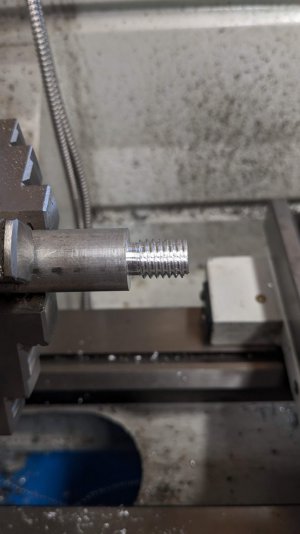
I know when I had the wrong gearing, the motor seemed quite weak. The load is basically higher. If you can change the gear box settings for the same thread setting, maybe we can empirically figure this out. Try the lower gear and see what happens.

Most of the Clough42 set ups are using 4Nm or less steppers. The original designs were somewhere around 3.2 - 3.5 Nm, if I recall correctly.

Maybe the load is too high. This can come from the wrong final gear ratio, or half nuts that are too tight. They have to be tight enough, but not so tight that they add a lot of friction load. Or your cable end ferules have too high of a resistance. Another thing could be pulley offset? So there's an inefficient power transfer? Of course, the motor or driver could be junk too, but it's not likely. I would change the threading gearbox settings and see if it behaves the way you expect. Do all three choices. If none of them seem correct, check the feed box settings, and see what happens. That's a lot easier to do than to rip open various gear boxes and count teeth.

Worse comes to worse, we can adjust the number of steps on the stepper. That's a last choice, since you are stating the motor seems weak. It shouldn't be "weak". It's not super easy for me to stop when running. I'm betting on gearing and or the half nut friction. Maybe you could try slightly loosening the half nut clamp tension a wee bit and see if the behavior is different.

If you have a current probe you could clamp around one of the A or B wires and measure the current through the stepper motor wires. The "A" setting on the driver is 7A, so I'd think you'd be able to see a decent amount of current in the wire. Only put one wire in the probe at a time! If you see low current, maybe it's the ferules. Either they are junk, or there's contaminants inside them, or you didn't crimp hard enough. Cut off the ferrules and just stuff the wires into the contacts, making sure there are no whiskers sticking out. That's all I did in the beginning and they work fine. If that works, find some quality ferules and crimpers. The crimpers are an important part of using ferules. Me, I'm just using the stranded wires. If they break, I'll eventually use ferules.
 
I was able to work on this some today. I was able to modify the black splash so that it fits back on now.

I would request to be able to set the X axis to direct read just like my dials are. I realize that the code to specify different scale resolutions per axis will be available to set when released.

I measured the ferules and got a few readings that might have been suspect so i cut all of them off and tinned up the wires. After re-assembly i didn't notice any difference with the ability to stall it by hand but then i did some test cuts and i was able to take .100 - .120" off from this aluminum without any issues so maybe my hand stopping force is a bad test??? I tested by trying to stop the carriage hand wheel both with the lead screw and power feed screw which didn't change much - in other words i don't think it's a tightness issue. I can't read the current with my meter is a clamp on inductive for amps for A/C only! I still think it feels under powered.

My lead screw is 8TPI.

The gearbox on my lathe is A - Direct, B - 1:2 or C - 2:1. Threading uses the same gearing but switches the output shaft so the thread chart is A - 26, B - 13 or C - 52. I've been running the gearbox in C for maximum torque. The stepper does not like moving the carriage in setting B at all as it's overdrive, and will do it under low load for A. C is where i've been testing with it as the stepper doesn't labor as much.

I messed around with a scrap of aluminum and put some 1/2 - 13 threads on it. The nut even screwed on!
 

Attachments

  • PXL_20230129_184150871(1).jpg
    PXL_20230129_184150871(1).jpg
    115.4 KB · Views: 50
Back
Top