Enco (RF30) 110v wiring

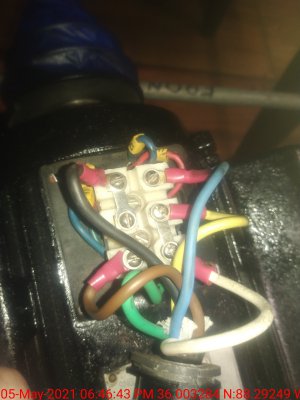
Yes that's how mine is on the motor just don't know where to put the wires on the switch

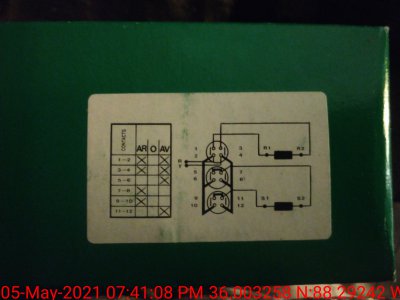
See if the picture of the drum switch (above in this post) helps. Not sure if you have the same factory wiring (colors, etc).

-Tom
 
Y
Hi Turner, can you post some pictures of your hardware? Closeups of the motor and switch terminals would help
Did you buy the new switch yourself or was it included with the machine? Do you have a multimeter available?
-Mark
I bought the switch myself...I couldn't find an exact replacement of course..yes I have a multimeter...the switch may not work the same as the old one I'm not sure and have no way of finding out since it's in 100 pieces and seem to be several missing
 
Y
Hi Turner, can you post some pictures of your hardware? Closeups of the motor and switch terminals would help
Did you buy the new switch yourself or was it included with the machine? Do you have a multimeter available?
-Mark
I bought the switch myself...I couldn't find an exact replacement of course..yes I have a multimeter...the switch may not work the same as the old one I'm not sure and have no way of finding out since it's in 100 pieces and seem to be several missing...
Hi Turner, can you post some pictures of your hardware? Closeups of the motor and switch terminals would help
Did you buy the new switch yourself or was it included with the machine? Do you have a multimeter available?
-Mark
 

Attachments

  • IMG_20210505_184642.jpg
    IMG_20210505_184642.jpg
    2.6 MB · Views: 11
  • IMG_20210505_184514.jpg
    IMG_20210505_184514.jpg
    1.7 MB · Views: 9
  • Screenshot_20210510-085038.png
    Screenshot_20210510-085038.png
    273.9 KB · Views: 5
  • Screenshot_20210510-085038.png
    Screenshot_20210510-085038.png
    273.9 KB · Views: 11
OK what you need to do then is "ring out" the switch using your ohmmeter. You put the switch on one of the positions and see what connects to what. Then you put it to the other position and do the same.
Make a chart of what you find and then we can hook it up.
-Mark
If any of that is unfamiliar just give a shout
 
Last edited:
I didn't see that other posting- is this the diagram for the switch you have?
If so, we are already there. The R1 and R2 go to the motor run windings, black and white (the strapped terminals)
The S1 and S2 go to the motor start leg, blue and brown. (swap if necessary for proper rotation)
The 120 volt power goes to the R and T
You need to attach several jumper wires (6 total) as shown between the various switch terminals
Ground wire is not shown but there should be one- tie to a screw on the motor case
-M
 

Attachments

  • Tnswitch.jpg
    Tnswitch.jpg
    3.7 MB · Views: 10
Last edited:
Y
Hi Turner, can you post some pictures of your hardware? Closeups of the motor and switch terminals would help
Did you buy the new switch yourself or was it included with the machine? Do you have a multimeter available?
-Mark
I bought the switch myself...I couldn't find an exact replacement of course..yes I have a multimeter...the switch may not work the same as the old one I'm not sure and have no way of finding out since it's in 100 pieces and seem to be several missing...
Hi Turner, can you post some pictures of your hardware? Closeups of the motor and switch terminals would help
Did you buy the new switch yourself or was it included with the machine? Do you have a multimeter available?
-Mark

OK what you need to do then is "ring out" the switch using your ohmmeter. You put the switch on one of the positions and see what connects to what. Then you put it to the other position and do the same.
Make a chart of what you find and then we can hook it up.
-Mark
If any of that is unfamiliar just give a shout

I didn't see that other posting- is this the diagram for the switch you have?
If so, we are already there. The R1 and R2 go to the motor run windings, black and white (the strapped terminals)
The S1 and S2 go to the motor start leg, blue and brown. (swap if necessary for proper rotation)
The 120 volt power goes to the R and T
You need to attach several jumper wires (6 total) as shown between the various switch terminals
Ground wire is not shown but there should be one- tie to a screw on the motor case
-M
Yes sir that's what I have I'm fixing to give it a try...the switch came with little metal jumpers on it, the old switch Used 5 jumper wires and two of them where connected with the black wire coming from the motor
 
Y

I bought the switch myself...I couldn't find an exact replacement of course..yes I have a multimeter...the switch may not work the same as the old one I'm not sure and have no way of finding out since it's in 100 pieces and seem to be several missing...


Yes sir that's what I have I'm fixing to give it a try...the switch came with little metal jumpers on it, the old switch Used 5 jumper wires and two of them where connected with the black wire coming from the motor
Awesome it works...what is the deal with the yellow wire is it only used in 220 or something?
 
Y

I bought the switch myself...I couldn't find an exact replacement of course..yes I have a multimeter...the switch may not work the same as the old one I'm not sure and have no way of finding out since it's in 100 pieces and seem to be several missing...


Yes sir that's what I have I'm fixing to give it a try...the switch came with little metal jumpers on it, the old switch Used 5 jumper wires and two of them where connected with the black wire coming from the motor

I didn't see that other posting- is this the diagram for the switch you have?
If so, we are already there. The R1 and R2 go to the motor run windings, black and white (the strapped terminals)
The S1 and S2 go to the motor start leg, blue and brown. (swap if necessary for proper rotation)
The 120 volt power goes to the R and T
You need to attach several jumper wires (6 total) as shown between the various switch terminals
Ground wire is not shown but there should be one- tie to a screw on the motor case
-M
Thank you mark it worked...can you tell me what the yellow wire is for?
 
Let me take a look, as you said it's probably an extra
Yes it's an extra one maybe for an accessory or light, just tape it up and ignore it
Glad you got it working!
 
Last edited:
Let me take a look, as you said it's probably an extra
Yes it's an extra one maybe for an accessory or light, just tape it up and ignore it
Glad you got it working!
10 4...Do you have any idea where I could find the depth gauge assembly this is all I have of it
 
Back
Top