- Joined
- Apr 30, 2015
- Messages
- 11,350
I would assume the transformer is getting power and just measure the output for now, for safety's sake
-M
-M

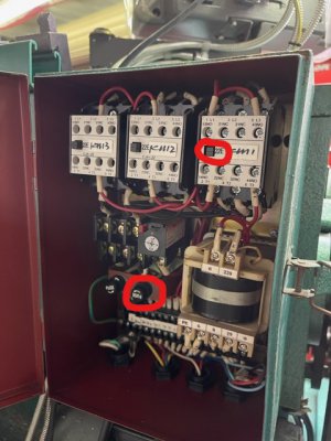
i made a mistake in the first post. that picture of the electrical box is one I got off the net that looked close to mine. When i went out this morning to follow your instructions i see now my transformer is different. going from left to right i have nothing on the first 3. I tried testing them across each other and to ground individually. I do have 29 on last 2. The Schematic is also one I got off the net, It says its for my machine but now im not so sure. Just FYI. I know very little about wiring so detailed info is a big help. thanksI’ll ask the obvious because I see a fuse in the bottom of the cabinet. Are both fuses good? Do you have a meter? In the picture if you put your meter leads across the two red wires on top of the transformer you should read 220 volts AC. On the bottom of the transformer reading across the first two wires on the left side you you should read 6 volts AC. Moving over to the next three wires on the bottom it looks like the first wire is white. Put one meter lead on it and read to each of the next two wires and you should get around 29 volts they way it looks
I did check the fuses with a meter and they are both good, I do get a reading of 29 between the 3rd and 4th WIRE, I do not get a reading between 3rd and 4th terminal. ( #2 is not used). I tested both the E stop and the green start/power buttons with a wire off and they both seem ok. I get continuity when pushed on green or pulled on E stop. Would it be ok to take one wire off the switch and connect it to the other wire to make the switches constant on for right now? that way when i power it on I should get juice to #6. and that should make it easier to test for power. Is that correct ?This pic is your actual transformer and you have 29 volts on the last two bottom terminals your transformer is OK. The first wire from left is yellow/green and looks to be labeled PE is ground. Do you get a reading between the third and fourth wire? I would look for maybe 6 volts that would be the power for the lights. The 29 volts on the last two terminals is for the relay coils.
Like Mark mentioned, it’s likely a safety switch gone bad. It could possibly be a relay coil bad but that is about as unlikely as a bad transformer.
Disconnect the power and go to each of the switches and remove one wire from the switch and then check for continuity across the switch terminals. You want the switch out of the circuit to test it that’s why I mention removing one wire.
‘Did you check the fuses? Check them for continuity with your meter.
after doing a bunch of testing and help from a friend who can read the schematic I figured out that I do have power going to coil in the KM1 relay but it is not pulling in. So just ordered 3 . Will update when i get them installed. Thanks so much for all the input.KM1 is the power latching relay, KM2 and KM3 are the motor run relays. KM1 should latch on power up with the spindle switch in the stop position or there is a start button, if not most likely it is a faulty contactor coil. Almost never see a transformer fail, in particular where the taps are fused. The indicator lights are 6V, if KM1 is closing it should latch. So I would check the function of that first. If there is a belt cover switch or guard switch which it looks like after the E-Stop switch then most likely that is faulty.
The pictures and schematic are too poor resolution to really see the details. When measuring the transformer voltages, you measure from the 0V tap to the voltage tap (6V, 29V). The red wires are the transformer voltages, basically you start out measuring voltage from the 0V to the 29V starting at the transformer terminal and at each step forward, wires numbered 1, 2, 3, 4 and 6. You would also measure voltages a A1 and A2 on the K1 power contactor to see if it is getting power to the coil. If there is power to the coil and it is not closing then the coil has failed (you can also disconnect A1 and A2 and measure the coil with an ohm meter and see if it is open). Be mindful that the black wires are hot with 230VAC so a short when probing voltages could be very serious. I would suggest if you do not know how to check the voltages that you find someone who is more familiar with electrical equipment. If one needs a contactor replacement, one would need the specific model number and possible checking the top contact block as to NO/NC configuration. There are Baomain AC contactors that seem to be the same style, but you world need to match up the same specifications and configuration. Most likely I would think their is an interlock switch that is either become misaligned or failed, you can put a jumper across the switch or check it with an ohm meter with the wires disconnected.
Just an example. https://www.amazon.com/Baomain-Contactor-CJX1-22-3-Phase-3-Pole/dp/B01J9MW0H0