Fadal monitor upgrade to LED

alloy

Dan, Retired old fart
H-M Supporter Gold Member
Joined
Jul 5, 2014
Messages
2,776
My monitor on my Fadal is getting dim and I'd like to replace it with an LED monitor. I did buy a monitor that has a BNC connector, but found out my monitor is VGA.

The new monitor has VGA inputs and I believe can be used with my VGA circuit board on the mill. But there isn't an available adapter cable available. The connector on the VGA pis is a 6 pin molex. Two things I need to do, get a molex connector with pigtails in it, and figure out what pins go to what on the VGA cable. On the Fadal FB group someone suggested just swapping the wires until I get a picture. I don't think that's such a good idea. The VGA board is part of my front panel circuit board and I really don't want to spend $1500 for a new board if I fry it and the majic smoke is released.

So, is there a way to determine what type of output the VGA pins have in order to adapt them to a 15 pic VGA connector?
vga out.jpgvga wires.jpg5 pin molex.jpg

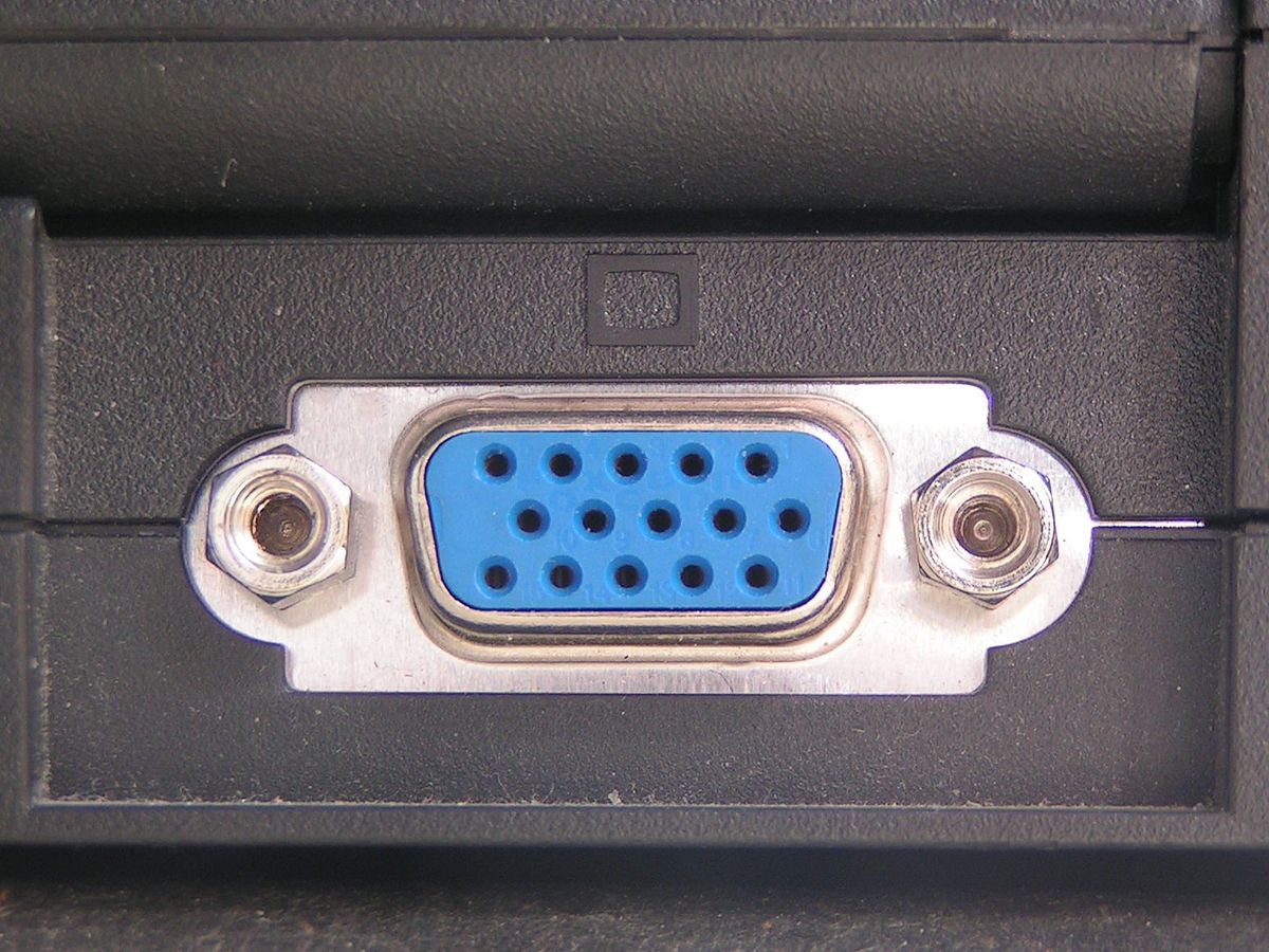
This connector is in the monitor board from the VGA output.
20220417_130647.jpg
 
Joe Pi has a series on his Fadal display;
 
Joe Pi has a series on his Fadal display;

I'm assuming you mean Joe Pieczynski on youtube?

He has 4 vids on setting up and some basic programming on a fadal I found, but his monitor upgrade has a BNC connection.

Do you have a link to the what you are referring to?
 
Last edited:
They describe upgrading them, but they use BNC connectors not VGA, might be more on replacement on the Practical Machinist. I tried to look up the schematic, but so many models and they do not show the pin out description of that specific connector. In some there seems to be a separate VGA interface board with a standard VGA cable connector going to the CRT.
 
I've saw previously those and I really appreciate the links but as I mentioned I do not have a BNC connector. Both of those vids reference BNC type connections

I have VGA and need to figure out the pin outs from the VGA board (see pic) to make an adapter cable to a standard VGA connector.
 
So, is there a way to determine what type of output the VGA pins have in order to adapt them to a 15 pic VGA connector?
The ground should be able to probed to ground , probly the fat trace on the pcb , then you need
red , green , blue, and maybe a sync pin.

You should be able to cut a vga cable in half to recycle for testing , once ground is conected you can try to get the sync pin conected and then figure out which way round rgb is.

Stu

Edit , you have osciloscope ?
 

Just 6 pins are needed:
Red, green, blue, H and V sync, and a ground
Sometimes the H and V are combined on one wire so only 5 would be needed
Usually the first 3 pins on a given connector are the three colors R,G,B
 
Last edited:
You might find the attached document helpful, based on what they describe, I am assuming the orange wire is the green (probably use a different color so not to confuse it with ground). Cable shield appears to be only grounded at the CRT end, depends, usually shielding is grounded at only one end for low level signals, but varies.

1650300692973.png
 

Attachments

  • CNCU_Manual.pdf
    534 KB · Views: 5
No I don't have an oscilloscope. I wouldn't know how to use it if I did.

The red and shield wires go from the connector to what I think is a transformer. (left bottom of pic) So I'm assuming black is ground, red must be power. That leaves H,V,R, and B, and probably shield (ground) to go to the new VGA connector for the monitor.

I've not been able to find the what I beleive to be a molex mxn-13 7880 connector. I'd like to get one with a pigtail as I don't have a way to crimp the small connectors on the wires that will fit in the molex connector.


monitor back2.jpg
 
If it is a monochrome display then the connections per the document posted would be below, a bit of a guess at the end of the day. Maybe email LCDPARTS.NET and they could help.
1650327806764.png
 
Back
Top