First whack at a gyroscope

WobblyHand

H-M Supporter - Diamond Member
H-M Lifetime Diamond Member
Joined
Dec 18, 2019
Messages
6,464
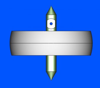
Thought I'd make a gyroscope for my grandson. Perhaps the first one will be for me, if it doesn't turn out well... Bought some 2" cast iron flywheels from Martin's Castings. After watching Clickspring's video on a gyroscope, I thought it might be possible for me to make one, although perhaps not as nice. Made a FreeCAD model just to give me some ideas of size and whatnot.
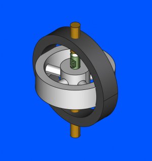
isoview_gyro.jpg
Ordered and received some 2.5" OD, 2" ID aluminum tubing for the cage. Found some 1144 for the shaft, and I hope I have some small diameter brass floating around for the "bearings". When I received the flywheel it looked a little off. Hope I can machine it true.

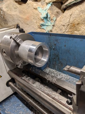
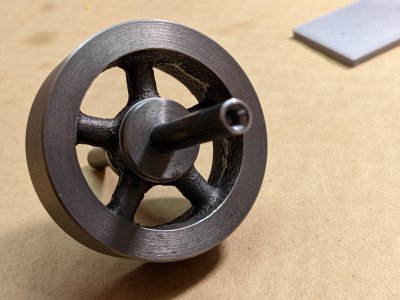
Today spent some time in the shop trying to grasp the flywheel. I found a face that was sort of flat and used that as a sort of reference. I then faced off the boss where the cast in letters were. Next was the outer face. Then I flipped it around and faced off the other side. Looking at everything it was clear that the wheel was pretty lumpy. I decided to put in the four jaw chuck and attempt to indicate on the inner hub. The hub was bumpy but I sort of got it somewhat dialed in. I then faced off the hub and rim again. Next I drilled the hub with a 7/32" drill and then a 15/64" drill and reamed it to 0.2500". The 1144 was 0.2495" and slipped into the hole. I then applied some cyanoacrilate glue. It didn't seem to want to set, so I lightly dusted the joint with some baking soda. This set the super glue.
I then turned the rim, which took a while, mostly because I wasn't sure how deep of a cut I could take with the glued shaft.

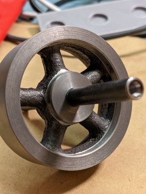
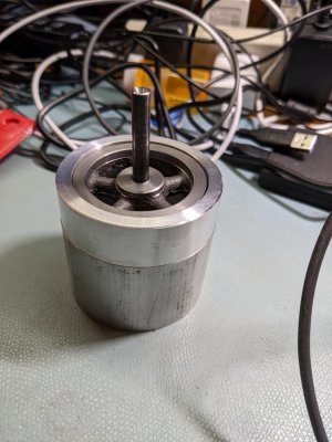
This is what I have so far.
PXL_20221129_005707798.jpg
It's not easy cleaning up the spokes. I can see that will take a while, at least with my low end needle files. And cast iron is messy. Think I will end up painting the spokes as they are not that attractive.

It's a start.
 
Be sure to balance it before painting and then again after.
For the final balance after painting, I have often used dabs of paint to add weight to the light side instead of trying to remove from the heavy side.
 
Last edited:
Use the shaft and bearings for this.

Make the shaft and bearings then build a fixture that can be mounted in a vise and make shaft perfectly level.

If bearings and alignment are perfect a drop of paint will make it turn.

This does 2 things.

Balance the wheel.

Confirms bearings are in alignment and minimal drag..

Good source of bearings are old hard drives and computer fans, made for speed and tight tolerance on hard drive ones.

The head arm looks to be easiest to harvest.

Sent from my SM-G781V using Tapatalk
 
Got the wheel to 2.0003", guess that is close enough to 2". After numerous failures, with other tooling (couldn't get the tool to the place I needed) discovered I could use a small boring bar to machine some of the inner rim. Spent some time hand filing some of the casting nurbs off. It's a little better.
PXL_20221130_015009170.jpg
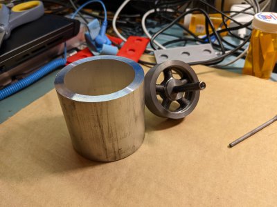
Next I sawed off a piece of thick wall aluminum tubing and faced off the ends. Clickspring recommends to keep it a bit long to act as a handle. I have about 2-1/4". The ID is smaller than 2" so I need to bore it out a little. I think I will set the clearance to about 0.020". This set me thinking about my CAD model, and the fact that I hadn't curved my flywheel to fit in the cage. So I sat down and figured out how to do a boolean cut of the flywheel with a sphere.
PXL_20221130_015051123.jpg
roundedflywheel.jpgPXL_20221130_015125181.jpg
Since I have a ball turner now, I can make an attempt at radiusing the wheel. The ball turner's flimsier than I would like, but I think I will be able to do what I need to do, taking baby cuts.

I found the brass rod and experimented with making a conical divot. Rapidly found out that the tool I had was not suitable. Found a 90 degree end mill and attached it to a #2 holder and tried that out. A bit more successful. As I stared at the rod thinking about threading it, I realized I hadn't thought through the threading on the upper and lower mounts. So it's back to the drawing board for me, to work out the details on the mounts. Think I want to draw the reduced diameter and how I intend to tighten the screws. Maybe I will knurl the ends and maybe round one end and make a small vee in the other.
 
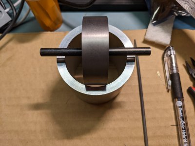
Turned the OD of the aluminum tubing until it was round, and then bored out the ID so the gap all the way around the flywheel is 0.5mm. For some reason the ID was not as smooth and polished looking as the OD. I obviously used different inserts, but the interior was sort of frosty. Thought it was the little 3/8" steel boring bar I was using, so I replaced it and used a carbide 1/2" bar. Same result. Even after installing a new insert. Finish is not rough, so I consider it done. Maybe I will polish it later.
PXL_20221130_202506991.jpgPXL_20221130_224919021.jpg
I would have finished up the aluminum ring, but I need to repair the DRO on my mill. The X-axis is funky and I need to take it off and inspect it. Didn't feel like it today, so I went on to the next part, one of the brass pieces. Made that on the lathe with my homemade ELS.
PXL_20221130_225021039.jpg
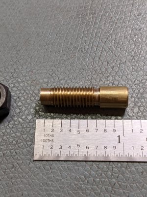
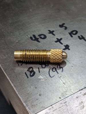
Came out OK so far, but I boxed myself into a corner. I didn't think through the order of operations. I had planned to knurl the end and maybe to turn a hemisphere on the end. I'll check, but I think I can't hold it well enough anymore. That will be for tomorrow. The thread is 1/4"-28. Tried using my thread micrometer on it, but I don't think I set the micrometer correctly. I think the pitch diameter is supposed to be 0.2225"-0.2258" for 2A. I measured 0.2300" and a 1/4"-28 nut went on without a problem. I'll have to play with the thread mike some more.

Still giggling about cutting the thread, just because of my ELS. I can't believe it works so well. What a sweet addition to a lathe.
 
Turned the OD of the aluminum tubing until it was round, and then bored out the ID so the gap all the way around the flywheel is 0.5mm.
Ahhhh.... so the outside face of the flywheel will be turned spherical not cylindrical so when you turn it 90-degrees from where you show it you won't have interference at the "corners".
That will look really great with the round gap between the two parts.

Came out OK so far, but I boxed myself into a corner. I didn't think through the order of operations. I had planned to knurl the end and maybe to turn a hemisphere on the end. I'll check, but I think I can't hold it well enough anymore. That will be for tomorrow.
Could you instead just chuck up a nut (long coupler nut preferred) and then thread your piece into that for finishing?

Congrats on the ELS success!

Brian
 
Ahhhh.... so the outside face of the flywheel will be turned spherical not cylindrical so when you turn it 90-degrees from where you show it you won't have interference at the "corners".
That will look really great with the round gap between the two parts.


Could you instead just chuck up a nut (long coupler nut preferred) and then thread your piece into that for finishing?

Congrats on the ELS success!

Brian
Yes, the flywheel will be turned to be spherical. Think it will be ok, especially for such a small gyro.

Good idea on using a long coupler nut. That should give me the extension I need away from the chuck so I can get the knurler there as well as the ball turner. It's kind of crowded near the chuck!

Without real bearings I don't know how well this will work but I'm giving it a try.

Edit: Thanks for the congratulations. The ELS was a 6 month project, so it has been immensely gratifying to have it work so well.
 
Last edited:
Coupler + nut + work piece. This worked great. Thanks @brino !
PXL_20221201_181507157.jpgPXL_20221201_173147070.jpg
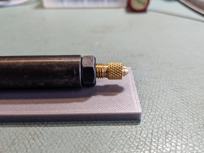
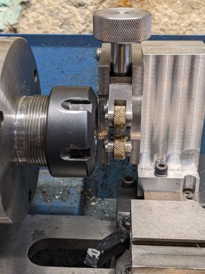
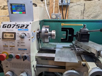
Over pressured the knurl. Ooops. Hard to remember when you haven't used it in a while. Did the operations on different lathes, because of the tooling. Knurler on the mini-lathe and ball turning on my G0752Z. The knurler wheels are 0.400 away from the ER32 nut on the mini-lathe. I made the knurler from @mikey 's project post. Love it. Makes knurling pretty easy.

The ball turner is kind of a wiggly affair but is ok for small cuts. 1/2" shank on the ball turner, but the body is made of aluminum. There's also no easy way to set up the position of the tool bit accurately. Wish there was some sort of rod I could line up to help out with that. The set screw holding the tool bit wants to rotate the tool bit away from level. :(
PXL_20221201_180711431.jpgPXL_20221201_180826929.jpg
On to the shorter version of the same piece. Hope there's enough threads to hold onto. Or, maybe I can do the piece in reverse. Knurl, then ball, then thread, part off and finally the 90 degree cone. That's if I can fit the knurled end into the collet. I'll have to check if that's possible.
 
Back
Top