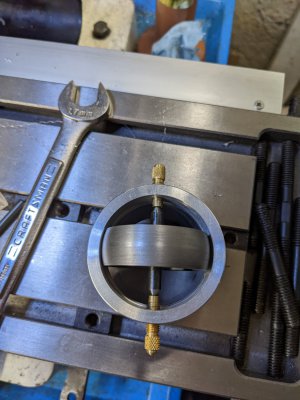
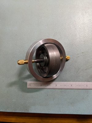
First whack at a gyroscope

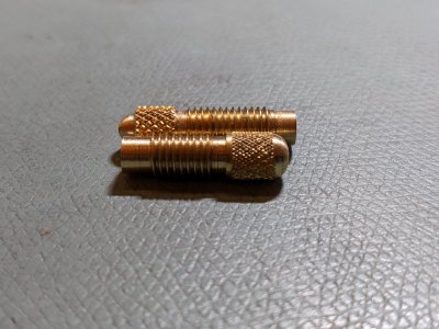
A little more progress. Made the shorter brass piece, but under knurled it, and the knurls didn't track. Kind of a fine knurl. Oh well, clearly knurling in brass takes some practice, and it's been a while. Doesn't matter for this, the piece is functional, so good enough for now. Took a lot less time, because this piece is similar to the first one I did. The rounded piece came out different radii, I don't know why, since I hadn't changed the cutter position. Have a bit to learn apparently. Lets just say the piece are is unique. :)
PXL_20221201_224210802.jpg
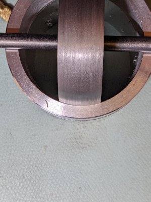
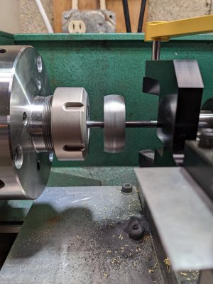
Then I tackled the flywheel. It's not super, but for a first go at this, I'll take it. Finish could have been better, but the shape is there! My first guess at the center where the cutter was off, so I had to adjust the Z to better center the cut. I just offset Z until the left cut width was equal to the right cut width. Is it good to the thousandth? Probably not. Now the profile of the wheel no longer fouls with the ring. Getting there.
PXL_20221201_222505619.jpgPXL_20221201_224701235.jpg
The only lathe work left is to cut down the shaft and point the ends. Got to fix the DRO on the mill. Hope that is just a cleaning job.
 
Last edited:
The DRO is more than a cleaning job. PM is sending a new read head. However, I decided to plunge ahead and get some more done.
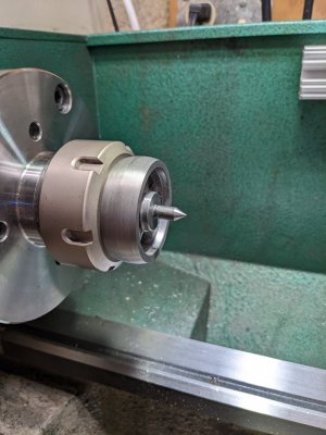
Parting off the shaft was mundane. I then cut a 60 degree cone on the cut off end.
PXL_20221207_203543635.jpg
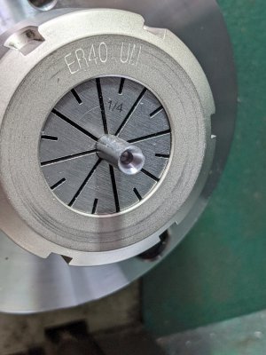
I needed to flip the piece around and thought there wasn't quite enough for the ER40 collet to grab on to. So using the same material as the shaft (actual same piece that I cut the shaft from) I made a 60 degree cone with a center drill.
PXL_20221207_203616685.jpg
Then I loosened the collet and pushed in the pointed end into the "socket". This way the collet was filled with the same diameter and I then clamped down the collet nut. Then I parted off the other end and made another 60 degree point.

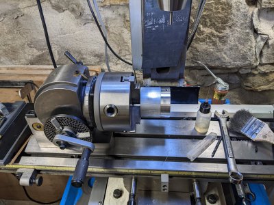
Next, went to the mill with a funky DRO and set up my dividing head. I put the aluminum tube which I had turned and expanded the chuck to grab it from the inside. I then drilled two holes with a #3 drill and tapped the holes to 1/4"-28, which matched the brass screws I made.
PXL_20221207_212802541.jpg
Then I removed the tubing, put it on the lathe, parted it off and finished the end and chamfered the edges. At this point, I couldn't resist putting it all together. So I did. I adjusted the screws to get the right amount of drag and gave the wheel a spin. And what do you know, it spun a bit. It spun even longer with a drop of oil in the "bearings", about 12 seconds with just a finger spinning the rim of the wheel.
PXL_20221207_220940697.jpg
That's it for today. Tomorrow, I need to spot face the shaft and drill a small hole for the string. Not sure how I am going to clamp the wheel and shaft, but that's tomorrows task. The gyro is a lot better than I expected.
PXL_20221207_223844336.jpg
 
Well it is done, but it isn't. Held it on the mill table on vee blocks. Kind of a janky set up. Had to find a piece of M6 all thread to make a new clamp as the supplied clamp screw was way too long and interfered with the mill ring light. The longest M6 bolt I had was 30mm, I needed about 50mm. Turned the bottom of the all thread smooth after looking at the stock screws and the rough bottoms. I then used a pair of M6 nuts jammed together to turn the stud to hold one end of the shaft.

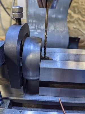
The flat I made is offset, drat. I figured that might happen. Had no way to center things up except by eye. The shaft was too deep in the vee to get an edge finder in. But I plowed ahead and used a spot drill for the hole, then drilled it. I had to go with a much larger hole because I needed drill length. The jobber drills were too short for this diameter. Ended up with a 3/32" drill held by the last 1/2" of the drill. Not ideal at all. If I make another one, I will need to rethink this.
PXL_20221208_163552628.jpg
The vee-block to the left is clamped to the table. Due to an over sight on my part, the right vee-block wasn't. I had just trammed my vise and didn't want to move it so I could get another tee nut in place. Survived this blunder, but hope not to do that again.

Looked everywhere in the house for some string! I was surprised to learn we had none, or at least my wife and I looked in all the usual places and found nothing. Finally I had a thought and remembered I had a roll of poly twine that I used for the garden. Grabbed a piece, melted the end a little and wound up the twine on the shaft and gave it a pull. It balanced and stood up for a while, but I didn't time it. The cage was rotating a lot with the flywheel, so much so that there was a "silver shell" about the gyro. Probably have way too much bearing friction.

Thought that was pretty cool and wanted to do it again. Managed to cut myself that time, seems that I had been touching the wheel at the time of the pull. Didn't hurt much but bruised a finger. Wondering if this is suitable for a little kid. Probably will have to ease off more of the edges than I already did. Think this may end up as more of a toy for my son-in-law than my grandson... Think it needs to be easier to spin.

My critique of the basic design is the length of the shafts are too short (3/8") to wind up much string. And poly twine is not a good choice for string. I will try to dab the bearings with some lithium grease with some molybdenum di-sulfide mixed in. Maybe that will help a little. Also the brass tends to move a little, so the bearing pressure isn't constant. I may lock one of the brass screws, although I really don't want to.
 
@WobblyHand ,

I will try to dab the bearings with some lithium grease with some molybdenum di-sulfide mixed in.
That sounds messy and perhaps not kid friendly.
When I made mine I found they needed to run for a little while to get smoother.
One thought is to spin them with compressed air a little to "bed them in" a little quicker.
Once that was done just a tiny amount of some good oil worked well. (I had Starrett on hand)
Also the moveable end would tighten/loosen depending on which way the string was wrapped.
I used some blue (non permanent) lock-tite to stiffen up the adjustment.

Wondering if this is suitable for a little kid.
It does depend on age, but this too can be a learning moment about having your fingers in the wrong place..... they won't do it twice.
I doubt they could pull hard enough to cause any real harm to themselves.
However this also depends on if Mom and Dad will let them play with it again after a little boo boo.

It looks great!
Brian
 
The flat I made is offset, drat. I figured that might happen. Had no way to center things up except by eye. The shaft was too deep in the vee to get an edge finder in
I think the vee blocks are usually made with the v centered... allowing one to edge find off the sides of the vee block itself.
 
I think the vee blocks are usually made with the v centered... allowing one to edge find off the sides of the vee block itself.
I'll have to check that for next time. Thanks.
 
This is very cool. I always wanted to build one of these with a motor in line with the flywheel. I'm thinking a 10K rpm electric model car motor. Instead of pulling a string just put jumper clips on the motor.
 
A blast of air too...

Sent from my SM-G781V using Tapatalk
 
  • Like
Reactions: rwm
Back
Top