Follow up question - Huanyang VFD - How to change Output Voltage - PD141 ??

Wow. Thank you. That worked. It runs as it should. I will now sift through them to identify their effect.
Is this vocabulary standard to VFD? Are the connections Are the control standard panel inputs and outputs relatively standard?
I am beginning to experiment with linuxcnc. I notice there is a 'spindle' configuration tab. Is it likely it can interface with the control panel?
Thank you, Dan
 
Is this vocabulary standard to VFD?
Well, kind of. Every manufacturer has their own idea about how things should be named, but they all work pretty much the same. It helps when you have had some experience with different units and different installations, but you should be able to wade through it.

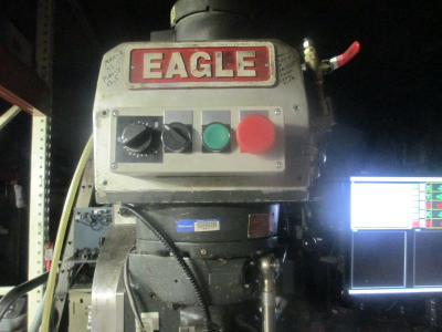
It shouldn't be too much problem interfacing with linuxcnc. The wiring diagrams should be in the VFD manual for the run commands. I frankly wouldn't worry too much about interfacing with linuxcnc, but rather just build a remote operator panel with a Start button, E-stop button, FOR/REV switch, and a Speed control pot on it.

Like I have mine now.
1615443061488.png

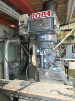
Or just mount the VFD on the head like I used to have mine.
1615443130471.png
 
So Jim: I tried to help answer here, but I think I was helping out wrong :) On my mill, I have voltage fixed, and adjust it by altering the frequency.

It seems that you're instructing him instead to also alter the voltage in some way? What is the advantage to doing both like that?
 
So Jim: I tried to help answer here, but I think I was helping out wrong :) On my mill, I have voltage fixed, and adjust it by altering the frequency.

It seems that you're instructing him instead to also alter the voltage in some way? What is the advantage to doing both like that?

All VFDs vary the output voltage along with the frequency as you make the speed adjustment, there is really a lot going on there. Exactly the way they do this is explained some excellent posts above.

If it were possible to adjust the frequency without adjusting the voltage, the motor current at lower speeds (frequencies) would go to astronomical levels and your motor would go up in smoke. That is a simplistic statement, but a good approximation of what would happen if the voltage was fixed at the line voltage and you were working with a pure sine wave.

What I was telling Dan to do is just setup the VFD parameters to match his motor. There was no real problem, but I know from experience that the HY VFDs come from the factory with many of the parameters set to unrealistic values, and in this case I don't know which were not set correctly, so I just went through all of the critical parameters and had Dan set them to realistic values without actually knowing what the factory setting was.
Interesting! I guess I have to re-visit my installs then! I have 2 VFDs configured with fixed-voltage(min voltage == max voltage) and adjust only the frequency to change the motor speed. I've not seen any problems yet with it, but it is good to know that I need to change that. Sounds like I have to spend more time in the manuals to figure out what I'm doing!
 
Unless you are using an oscilloscope to measure the voltage you are not getting an accurate reading, as far as I know there are no multimeters that will properly measure a PWM waveform.

The VFD will only apply enough current (torque) to spin the motor at the set rpm. As the load goes up, the power requirement will increase and the voltage (and thus the current) will increase as needed.

With some slip comp plugged in, I would expect that motor to turn at around 1800 RPM @60Hz with no load. Adding slip comp should tighten it up a bit.

If your VFD has sensorless vector mode, then get that setup and your machine will be happy.

Fluke makes a bunch of multimeters with LPF options to specifically measure drive PWM output. But you are right, your off the shelf multimeter will not measure it correctly. I own a scope at home (Siglent) that I was testing on a VFD just today I could never quite get the Volts-RMS reading to match the drive's set output voltage, it was always 30V or so higher. We have some Fluke 190 series ScopeMeters at work with a special V-PWM-RMS measurement option that nails the reading perfectly to the drive.

Sensorless Vector mode is the move if your drive supports it for sure.
 
Back
Top