G0704 (sort of) CNC'ing

Re: G0704 CNC'ing

Well, the 48v 600w power supply I ordered showed up yesterday.
Pulled out the 24, and stuffed this one in loose.

I got almost double the rapids on my X&Y! Z sadly has made no change. Stuck at about 35 in/min before the motor stalls. Mind you, at that speed, I'm pretty sure I could climb on top of it and it'd still move!

I'm going to pull the enclosure apart (yes, the one above) and redo it. I got a good deal on a pair of 12*12*6 (vs the 4 I currently have). Attached them to each other with conduit. I'll put the 120 A/C stuff in one, and the controllers etc in the other. Then just run a couple of DC lines from one cabinet to the other. It's just getting too crowded, and now I'm looking at adding more (4th axis, C6 spindle control, C3 speed feedback, touch probe interface.... etc!) so it was just nuts.
 
Re: G0704 CNC'ing

Small follow up...

Had a thread going over at cnczone. Seems the speeds on my Z are going to stay where they are until I replace the motor. Lotsa torque, but no speed on it. Just is what it is. Oh well! :)
 
Go home mill... you're drunk!

[video=youtube;Hcm6tdJFbbE]http://www.youtube.com/watch?v=Hcm6tdJFbbE[/video]

:))
 
Boredom + spreadsheet + finding a price list for your machine =

Retail for the whole machine ~$1600
Parts price total for the machine ~$8700

Hmmm... I either need to buy a whack of these and sell them for parts, or.... :rofl:
 
Re: G0704 CNC'ing

. I used those on my CNC router project (look up the user dr.fiero on YouTube) and was quite impressed.

Did I leave anything out? Ask away....

Nice conversion, and useful thread.

I looked up dr.fiero unsuccessfully. Could you post a direct link perhaps?

Thanks, Marco.
 
Tiny update - got my C10 board from CNC4PC to replace the "cheap Chinese BOB" as Arturo put it.

Got that hooked up to my C6 (spindle speed control), which NOW (FINALLY!!!!) works! Yay!

Now on to the C3 to detect speed, and give feedback to Mach.
 
Re: G0704 CNC'ing

Hey whatcha know... Forgot about this thread!

So, I hooked up the C3 board, and surprise! Didn't work.
Hooked my scope up to various spots - could see pulses at what looked to be about the right rate. Finally decided that the rate was just too damn high. So, with careful engineering, and meticulous use of fine motor skills (hahahaha) I whipped out the roll of electrical tape and an exacto knife... And covered up 15 of the 16 holes in the stock wheel. If you're doing the same, make sure to wipe down the wheel with brake clean to get every trace of oil off. If the tape comes loose it could smack up your pickup.

Poof! Worked like a charm. I had rpm feedback going into Mach.
A quick spindle calibration run, turned on closed loop.... Now the spindle will maintain rpm with or without load. Wheeeeee!!!! :D


Oh, side note... I used the stock opto that normally feeds the front panel, to feed the C3 board. No point in reinventing the wheel on that one (mounting wise etc). I'm going to experiment with a Y coupling to see if I can run the C3 and the stock display at the same time. No real point, it's just a dead black space otherwise. Maybe I'll put a clock in there instead. :D
 
As I was saying a few posts up, the control box was getting a bit (ok, a LOT) crowded
So even though I'd cut a whole two holes with the setup... I tore it completely apart and started over! :nuts:

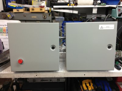
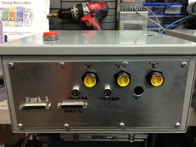
Here's what it looks like from the outside right now (I haven't added the cooling fans in the doors):
IMG_0013r.JPG
12*12*6, with 2X 1/2 conduit connecting them together

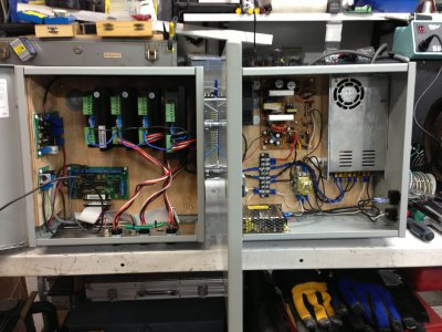
Inside(s):
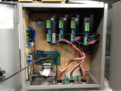
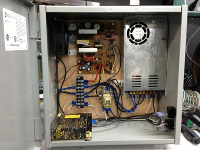
IMG_0014r.JPGIMG_0015r.JPGIMG_0016r.JPG
Now sporting a 4th driver for the "A". C3 & C6 on the side (hard to see), single C10 BOB with a 2nd still in the mail.
3 separate P/S's on the right (modded ATX for +5&+12, 48V, and a standalone +12V for the C6 board).


And the end panel underneath the l/h cabinet:
IMG_0018r.JPG
(obviously not completed!)

But... there's the 3 X/Y/Z's along the top, 3 more 5 pin connectors below that for tach and spindle speed, limit switches, and the "A" axis (that'd be the hole!).
Then there's 2 DB25's underneath for the parallel port hook ups. Sure glad I used the mill to cut those holes out! Fiddly.

Anyhow - this now keeps all the AC stuff in the one cabinet, and all the control in the other. Steel cabinets I'm hoping will give a bit of (emi) noise isolation.

IMG_0013r.JPG IMG_0014r.JPG IMG_0015r.JPG IMG_0016r.JPG IMG_0018r.JPG
 
Not a lot to add for the day...

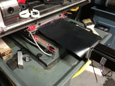
Was bugging me about debris falling into the front of the "Y" opening, so I added a flap similar to the back:
IMG_0022.JPG

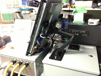
Was trying to make up a mount (in my head) for sticking my touchscreen onto the electrical cabinet.
Started to measure some existing screw holes out, then it dawned on me that the 75mm pattern I was measuring... was a VESA mount!
Popped down to the corner discount store, and for $29 grabbed a mount off the shelf. Bolted it to the cabinet - done!

IMG_0023.JPG

Added bonus, is now it obviously tilts all over, pulls in/out etc!

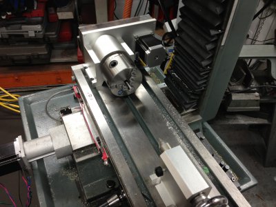
Oh yeah, my 4th (rotary) axis showed up the other day:
IMG_0021.JPG
With it's tail stock.

IMG_0022.JPG IMG_0023.JPG IMG_0021.JPG
 
Back
Top