granite dresser tops for a surface plate or for lapping?

upload_2015-2-16_20-15-47.jpeg
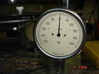
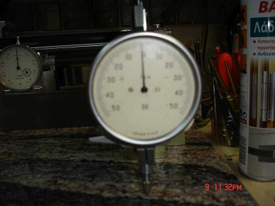
Fig 1 1µm Comparator by IZMERON

The method for verifying the epipedometro using the facilities available,
including instruments and knowledge, is as follows.
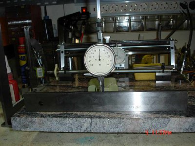
Using a 1μm resolution dial comparator,mounted on a height gauge by an adapter i made
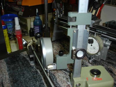
DSC00363 dial ind on height comparatop.jpg
Fig 2 Dial ind on height comparator

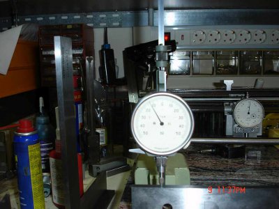
I measured the sagitta (bending) at the center and at intervals of 2cm along the length of the rod.This
is another rod for the demonstration. DSC00361 res Pic 1.jpg Fig 3 Measuring the straightness
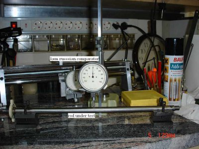
The rod is supported on V blocks.The measurement was taken by rotating carefully the rod and noting the max deviation.
First measurements showed a sagitta of 4μm that is a deviation of 2μm from straightness. It may seem brutal,
but i bent the rod by hand pressure, mounted on the V blocks using soft pads in the V and very easily,after only 2 attempts
there was no sensible movement of the dial comparator needle,all along the length.The measurement is rather difficult.
Temp was 20o C but the slightest vibration from passing cars affects it though my cave is on concrete floor.
I will continue,if there is any interest.
Ariscats
 
Yes please I am very interested.
I know what you mean regarding vibration as that and air currents both disturb my readings.
 
For savarin. Because the shop has central heating and is well insulated including double glass panels in the windows,
the remaining problem of vibrations is confronted by taking measurements late after midnight when traffic is
sparse.Any way taking measurements at 1μm level is very difficult with mechanical only means outside a metro
logy lab.Mind you,a micron is 0.04 tenths.But even a ten times uncertainty is enough for me.This is a hobby shop
after all.Probably my past training as a physicist has something to do with my love for precise measurements.
More photos will follow if you like so.
Ariscats
 
I use the spherometers to get close then change over to Foucault and Ronchi tests.
Thats when I use a cloth tunnel to stop the air currents. Both those tests show the differing air temperatures as black waves wafting across the glass
More photos are always welcome.
 
This thread has gone from some one finding a old broken down piece of furniture with a granite top to black waves wafting across glass and spherometers. Only on a hobbyist machinist forum. :) Just kidding guys....ariscats that is a very interesting measurement system. I may have missed something but is there deflection or sag and how do you allow for it when checking a surface.

Regards
Darrell
 
For Darrell .Thank you for your words and the kidding.It is normal,to my opinion, for friendly conversations to drift
around a little bit. Any way if there is a problem i will ask for the moderators to relocate, as appropriate.I did not
wanted to cannibalize the thread but there were some people subscribed to this, probably curious about the
epipedometro so i thought that this was the way for them to follow the discussion. As for the sagging now:


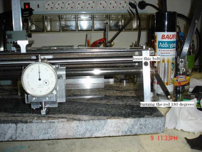
DSC00373 avoiding sag.jpg
The bolt noted and the other one on the other side,are loosened just a bit an then using a punch as lever the rod is rotated slowly and the indicator
observed,verifying any Sag.If there is one(never observed to this day) you turn the rod only 90 degrees and verify against previous measurements.
Any suggestions for something better will be highly appreciated.
Thanks again.
Ariscats
 
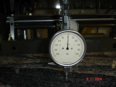
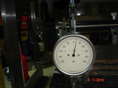
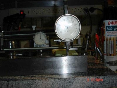
To savarin. See some photos of a self referencing measurements conceptually close to spherometer ones.DSC00369 self ref center.jpg
using the height indicator.This is a photo on the cender of the slab.DSC00371self ref left.jpg
and this one on the left side.It is 4 μm indicated(that is 0.16 tenths higher.

DSC00370self  ref right.jpg
this is the right side almost 2μm lower . Sorry for bad picture. Now just for a demo i measured a straight ruler class 2 accuracy 320 mm long
and the results are as follows:DSC00375 checking a class 2 straightedge cen.jpg
Center
DSC00376 checking a class 2 straightedge left.jpg
Left 13 μm deviation.
DSC00377checking a class 2 straightedge right.jpg
right, 25 μm deviation That is enough proof,to me, that the instrument measures something,at least.
In many years ago i attemptent to grind a mirror but i did not poses the required insistence to finish the job.
For the time I use a 115 mm Newtonian for occasional observation of planets mainly,from my balcony in city
Light pollution.Mainly for educating the young generation to the Mysteries of the heavens.At the time both
Jupiter and Saturn are visible from my place early in the evenings.
Greetings
Ariscats
 
Aricats, thank you for the pics and explanation. When I first looked at your measuring device it appeared longer than I believe it actually is. Hence my question about sag. It seemed the weight of the indicator and its mount could induce some sag when moved to the center of the rod. Obviously the clever way the mount is moved removing any external hand pressure takes away another variable. Very nicely done.
I really hope you saw my attempt to have a little fun at you and savarin's expense was just that.... good friendly fun. Nothing wrong with it being in this thread as far as I am concerned.


Regards
Darrell
 
No offense here mate, I just thought it was an exclamation of wonderment at how far this thread had spread.
As a lifelong digressor I'm used to going off at a tangent.:D
But continuing in the same vein we have traveled, when we measure optical flats for "flatness" we use another flat of known flatness and compare the interference bands they produce under monochromatic light. I have never done this. Yet.:eek:
 
  • Like
Reactions: 18w
to 18W No offense taken ,so no apologies needed Darrell.Hope that explanation was enough.Hope to see your Projects soon.
Ariscats
 
  • Like
Reactions: 18w
Back
Top