Group Project: Dividing Head - Organization and Design

So that begs the question of whether the spindle should be threaded at all. If left raw, how would the front indexing plate (or, should we call it the Quick Indexing Plate) be attached?

I'm starting to think that the 1.5" CRS that I made the spindle I have from is not appropriate for this project. While I could drill it for a roll pin to indicate the rotary position of a Quick Indexing Plate, there would be no shoulder for it to indicate against. If I switched to a 2" round, then I could make it match the spindle on my Atlas, including the MT3 taper on the inside. That would give me the flexibility to use all my tooling, since my mill is also MT3. For other members, I'd leave it raw to do that part as they see fit, but there still wouldn't be room for a 5C draw bar would there?


I would thread it. Find a common thread for this size chuck. But I also wouldn't mind if the part came to me with just a mount for the indexing plate. It's not a big deal to chuck it up and make it match whatever I want it to. Swearing at the 4-jaw and blaming the indicator is part of the experience. :)

The only MT3 tooling I have is for the lathe tailstock, so I'm not sure how useful it would be for me, but I know there are collets and such. If you use a 2" round, I would probably cut an R8 taper in there for the same reason you mention MT3, my mill has R8 tooling that might be useful in there. All of them would need a draw bar, so it would need some space on the other end to mount one if you want to go that way.
 
You can add me to the list of people who will manufacture one (or two) of the parts. I just need a drawing with tolerances on it.
 
In a perfect design, the gear and the worm would be brass?
First, we'd need to define "perfect", then recognize that it is the enemy of "good enough". :)
IMHO, "perfect" should include the question, "Do I have any on the shelf?"
After that, the brass/bronze does have a lower coefficient of friction, but this gear should never be used at high speed or under load. Otherwise you're doing it in what many call "The Wrong Way". :)
Brass/bronze may be stronger that some Al alloys, but what I've got is 7071. Stronger than some steels, and again don't do it "The Wrong Way" and the materials strength will be moot.
Brass/bronze is more corrosion resistant. If a member planning to use this on a ship, I think that would be important. I could possibly set up an anodizing station again?
There could be another design consideration that I have not taken into account, but "What I've got" is a pretty hard hurdle to jump.

Mark's base proved to be inadequate and he added a support. The base should be redesigned. Do you think a horizontal/vertical rotary table would be an easier project?
Robert

Agreed. The second point in my first post of this thread was a suggestion to reduce the length of the trunnion so that the base extension would not be necessary. The 1/4" thick plate that is the second support could be bolted directly to the main plate instead.
 
Last edited:
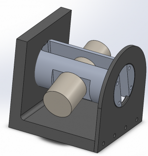
No one is volunteering to do the drawing, and people are understandably unwilling to commit to an unknown, so I'm going to start work on a drawing this evening. It will be in SolidWorks ('cause that's what I'm used to) and serve as a starting point/discussion aid.
 
Woohoo! Just checked the last haul I got from my uncle's house. He has a yard that would set all your hearts a-flutter. Chunks of steel everywhere. Almost all of it is exclusively A36, of course. He was a crane operator that was a magnet for scraps.

Anyway, I've got a 3ft length of 2" round. I'll probably need to take 1/8" off the diameter to clean it up and have it run true, but that should leave plenty for our purposes.
 
This is as far as I got this evening. Lot's of features of SolidWorks that I've never even looked at, so while I have prints, I haven't figured out how to add the dimensions to them.

Comments / suggestions / feature requests / snarky jabs?

Screenshot (3).png
 

Attachments

  • DividingHead.pdf
    80.9 KB · Views: 13
Interesting so far! You might consider making the left "L" material out of 2 flats so that it can better flat-pack in a shipping box though. Still having a hard time envisioning how that is going to work though.
 
I guess I wasn't as sleepy as I thought.

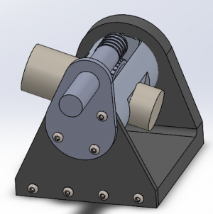
I see where you're going there, @ErichKeane, but I would think the stiffness would be severely compromised if both the supports were bolted on. I have a piece of 6"x6"x3/4" angle from my uncle that is about 10" long. He had another 20ft of the beam. Cut it down to the size that we need, and it still fits in one of the USPS flat rate boxes. :) But, weight and size was a concern I was thinking about, so how about this instead?

All screws so far are 3/4" long, 1/4-28 socket head. I think with a 3/4" base, it might be possible to go up to 3/8" hardware.
The main base is 3/4". It needs mounting slots. The trunnion can possibly be lowered .25 to .5 inches, for more stiffness and less weight.
The spindle has a 1.75" nose, and a 1.5" body. It needs threading on the tail. Not sure about the nose. And I haven't even started on the nut.
The trunnion cap and crank are 1/4".
I need to work in a spindle lock. Can it mount directly to the trunnion?

The trunnion crank needs a pin that indicates on the auxiliary support so the head can be locked horizontal, vertical, or in between at 5 degree increments?


Screenshot (7).png


Screenshot (4).png
 
I guess I don't have a good idea of scale either then :) As far as screw size: 1/4-20 is a bit cheaper/easier/more common typically, so it might be worth doing that.

As far as the base: What do you mean by mounting slots? What sort of thing were you thinking? I have a shaper that can do interesting shapes (was just watching someone do T slots!), so I could perhaps help.

I still can't envision how this works, so sorry if these are dumb questions/suggestions...
 
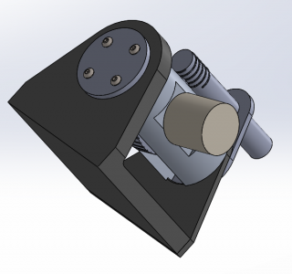
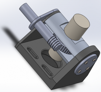
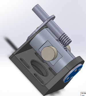
Maybe this will help. A faceplate or chuck is mounted on the big yellow knob stick up in this picture. I added mounting slots to the bottom.

Screenshot (10).png


The round bar coming in from the side is a worm, driving the gear that holds the spindle (which is vertical in this shot). The round hole in the bottom is just to remove weight.

Now, in this picture, the trunnion has been rotated so that the worm is on top, and the spindle will be horizontal. This is the back side, and the chuck would be mounted on the far side.

Screenshot (11).png


Make sure you read the thread where Mark_f, the inspiration for this one, documented his build.
 
Back
Top