Hendey Gearhead Lathes

682bear

H-M Supporter - Gold Member
H-M Supporter Gold Member
Joined
Nov 28, 2016
Messages
2,352
I'll call this 'A Tale of Two Hendeys'...

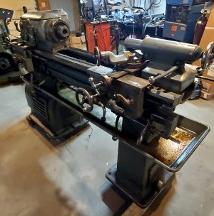
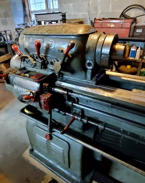
I've rescued two Hendey gearhead lathes from being scrapped. They are both 12" x 30" models, one was built in 1940, the other in 1944.

Just for a not-so-quick rundown on what I've found out so far...

The 1940...
20230215_081814.jpg

20230215_081830.jpg
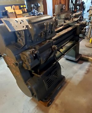
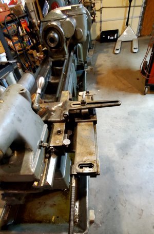
This lathe was originally purchased by Colt Firearms in 1940. It is called a 12" swing, but was ordered as a 'raised swing' model, actually giving 14 ½". It has an L-01 spindle with ball bearings, and has a taper attachment.
20230215_081843.jpg

It originally came with a 5hp 220v 2 phase motor, which has been replaced with a much newer 5hp Dayton 220v 3 phase motor. There is minor wear on the ways, and the cross slide feed clutch handle has been broken off. The lower control rod pivot bracket is also broken. The main power box and magnetic starter is also missing. Aside from all that, it appears to be in decent condition.

The 1944...
20230215_081657.jpg

20230215_081757.jpg
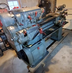
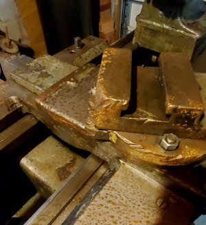
This lathe was originally sold to a high school shop in Pennsylvania... as evidenced by the condition of the compound...
20230215_081927.jpg

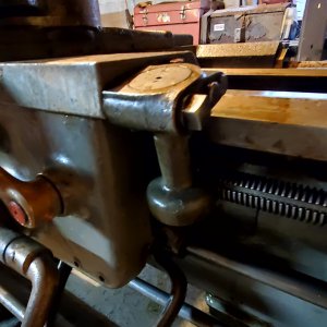
It is also a 'raised swing' model, with the L-01 spindle nose, but this one was ordered with the Timken roller bearing spindle. It was also ordered with a thread dial... which is uncommon for Hendeys...
20230215_081715.jpg

This is the first Hendey thread dial I've ever seen. It still has the original Continental 2hp 220v 3 phase motor. Again, there is minor wear on the ways, but otherwise appears to be complete and in decent running condition.

My plan for the two lathes is to attempt to get both running and evaluate the useability, then build one lathe from the two.

I don't think the '44 will need much... if not, I may end up building two lathes...

-Bear
 
So any idea why thread dials were not a regular item on a Hendey? Did they not expect their machines to used for much threading or real machinists didn’t use thread dials or something? Just curious.

-frank
 
So any idea why thread dials were not a regular item on a Hendey? Did they not expect their machines to used for much threading or real machinists didn’t use thread dials or something? Just curious.

-frank

Hendey lathes are designed to cut threads without the use of a dial. Once the half nuts are engaged, they aren't disengaged until thread cutting is finished.

Once you finish a cut, the lead screw is disengaged with a lever, the cross slide is backed out, the feed reversed with the same lever back to the start point, the cross slide is returned to zero, then the feed engaged with the lever again...

Since the half nuts are never disengaged, the tool always follows the same path.

It is actually easier... and faster, once you do it a few times.

I'm guessing that this lathe was ordered with a dial because it was going to a school... and they wanted to be able to teach the conventional way of cutting threads.
-Bear
 
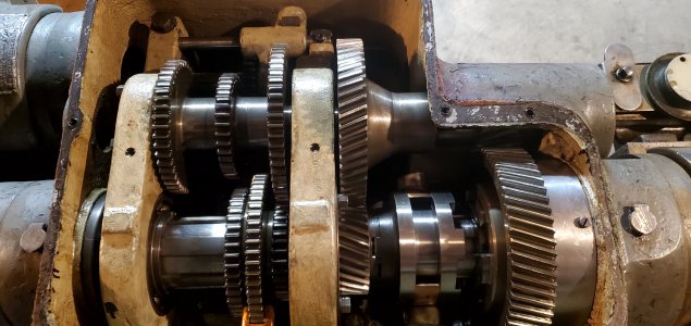
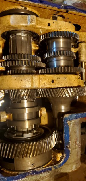
I had a little while to tinker with the lathes this morning, so I pulled the top cover off both headstocks.

The '40...

20230217_081229.jpg

The '44...

20230217_081304.jpg

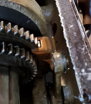
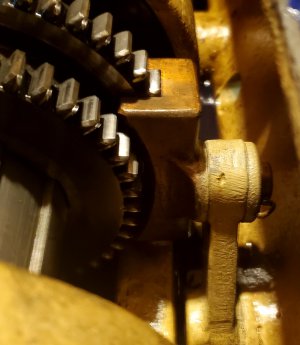
They are both clean and everything looks very good with one exception... on the '44, the gear in the center left looks like one side has been hot enough to turn the teeth blue... I can't see any way that could happen inside the gearbox. Maybe it is still discolored from when Hendey heat treated the gear when it was made?

I noticed a few parts on the '44 that weren't finished as nicely as the same parts on the '40, for example, the shift forks on the '40 were rounded and smoothly polished...

20230217_081249.jpg

...where the shift forks on the '44 were left square with the saw marks still visible...

20230217_081328.jpg

The '44 was a wartime production... maybe they didn't have the manpower to dedicate to low priority details? Or possibly they were having to build them faster to fill orders due to the increase in manufacturing to support the war effort?

I don't know... I'm just guessing... it's interesting, anyway.

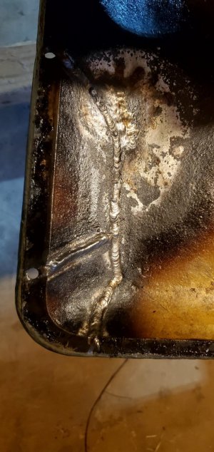
The '44 also has a very well done repair on the top cover...

20230217_082814.jpg

It is completely invisible from the outside.

-Bear
 
Nice lathes.
I have never heard anything bad about those old Hendeys.
I would want a thread dial tho. No ifs and or buts about that.
I wonder if they measured their lathes like Monarch did.
The 10EE swings 12 1/2" and the 12CK swings 14 1/2".
When I was looking to buy a lathe, Hendy was on the list of brands I was considering.

Yes, both of these will swing 14 ½"...

The other thing these lathes have in common with the Monarchs is how heavy they are built... they are pretty close to 3000 pounds each... that's a lot of weight for a lathe that size. My 12" Hendey tiebar lathe is maybe 1200 pounds or a little more... my South Bend 14 ½ is around 1800, I think...

-Bear
 
We (my wife, both daughters, and myself) spent this week in Hawaii for a much needed vacation. We have now been in all 50 states... Hawaii was our 50th. We had a great time and saw a lot of interesting things, including Pearl Harbor, the Pali Overlook, the Dole Plantation, and even took a ride on a submarine while we were there.

Before we left, I decided to see if the '44 model Hendey would run... I disconnected my old Taft-Peirce surface grinder and moved it, then moved '44 in it's place and wired it into the 3 phase system... turned it on, and... nothing...

The breaker was tripped... I reset it and it immediately tripped again. I spent an hour or so going through the wiring on the machine looking for issues and found none... I eventually discovered that the breaker was bad. It would trip with no current on the system.

Not having a spare breaker, I disconnected the power wire from my big drill press and wired it to the lathe...

It runs...! But it doesn't run like it should...

The spindle turns, but very slowly, and I can stop it with my hand. That led me to look at the spindle clutch, which was WAY out of adjustment. I adjusted the clutch and now the lathe runs great, but the clutch has a spring loaded pin that 'locks' the adjusting collar to keep it in adjustment. That pin is sheared off...

I left it there... I'll have to disassemble the clutch to get the pin out, then see if I can machine a new pin. I'll try to get to that this next week, but our clothes dryer has quit, so repairing or replacing it will have to take priority.

Sorry, I didn't get any pictures... I'll take a few and post them later.

-Bear
 
I spent most of the morning attempting to repair an ornery clothes dryer... so I didn't get a lot of time to tinker with the lathes.

I did get some pictures, though.

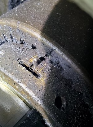
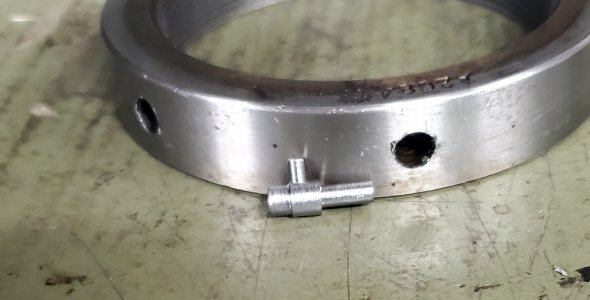
This is the pin that is sheared off in the '44...

20230227_103830.jpg

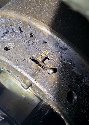
This is the same pin in the '40...

20230227_103846.jpg

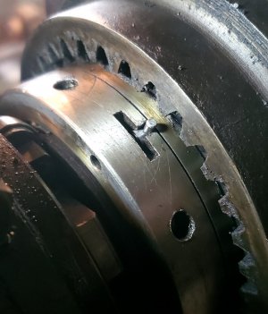
It is basically a 'T' shaped pin. To adjust the clutch, you pull it back and rotate the leg of the T into the slot, like this...

20230227_103940.jpg

... then turn the collar that the pin is mounted in to adjust the clutch. Then the pin is rotated up until it slips back into the notch... this keeps the clutch adjustment locked.

It looks like the pin on the '44 broke off just behind the leg of the T... the leg and the front of the pin are missing.

I don't think it will be difficult to make the pin... the hard part will be taking the clutch assembly out to get to the pin. I began disassembling the '40 and reached a point where I need a large puller... I have three pullers now, but none are big enough. I'll have to see what I can come up with.

I can't really tell exactly how the clutch assembly is removed... the best I can figure, it should just slide off the shaft... with an appropriate puller... it is built into the hub of the upper v-belt pulley.

-Bear
 
I decided before I get too deep in the disassembly, I should probably evaluate the other systems on the lathes... and I found some more issues with the '44.

I engaged the feed, turning the spindle forward by hand until the carriage began moving... but then when I turned the spindle backwards, I would have to go 10 to 12 full turns of the spindle before the carriage would start moving the other direction... something isn't right...

I disengaged the feed and engaged the half nuts and repeated the test... I only had to go about 1 turn before the carriage reversed, but it took several turns for the handwheel to begin moving. The handwheel also has a good bit of play. This led me to see if the handwheel disconnect was fully engaged... and I discovered the disconnect has been removed and replaced with a washer and bolt... hmmm...

Also, the feed clutch handle won't move all the way to the engaged position, and has to be held up... with a decent amount of force.

I think there are several issues inside the apron...

I've also discovered that the feed reversing mechanism has a lot of slop and doesn't operate smoothly.

I then repeated all of these tests on the '40... it passed them all easily. The controls on the '40 are much smoother and much more functional... except for the cross slide feed clutch lever, which was broken off in shipping, so I can't test it.

So... with all this in mind, I think I'll head in a different direction and work to get the '40 operational instead of the '44, which likely will become a 'parts donor'.

The cross slide feed lever will be an easy fix... there is one taper pin holding the lever, so it's an easy swap.

But... the '40 doesn't have any electrics left. It has an apparently new 5hp Dayton motor that hasn't been wired up. I have a main power disconnect and a contactor that was removed from a K&T mill that was scrapped. I plan to use them... maybe... if they are rated to run the 5hp motor. If they aren't, I'll probably swap in the 3hp GE motor that came off the K&T also...

Anyway, I have a good bit of work to do before I can power up the '40... but at least I shouldn't have to disassemble the spindle clutch to swap a pin... the pin in the '40 is good.

-Bear
 
I guess I've reversed course again...

I started attempting to remove the broken cross feed handle stub from the '40... I removed the tapered pin, but the stub won't budge. I'll probably have to drill and tap it and use a slide hammer to pull it.

As I was working on that, I walked by the '44 and tried engaging the carriage feed handle again. To my surprise, it engaged easily... I couldn't get it to engage the other day. There is a lockout rod in the apron that prevents engaging the feed and the half nuts together... I'm guessing the lockout probably isn't operating like it should. I powered the lathe up and ran through all the feeds... it works great now that the feed handle will engage.

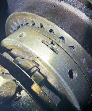
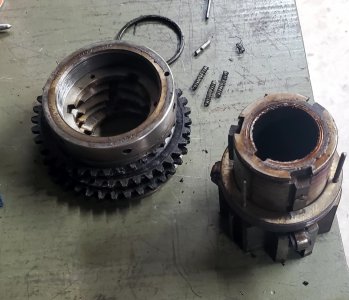
So, I went ahead and removed and disassembled the spindle clutch on the '44...

20230306_084441.jpg

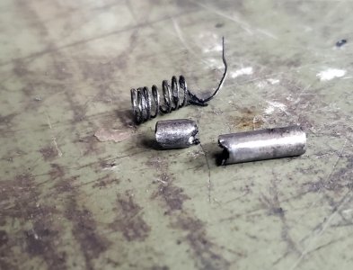
and machined a replacement adjustment pin. The broken pin...

20230306_084454.jpg

...is not the original pin. It appears to be homemade from a piece of 1/8" diameter mild steel.

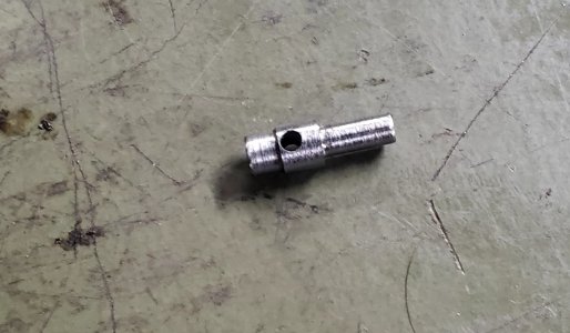
I reverse engineered a pin to fit the clutch and turned it from a 1/4" bolt... then turned a 0.1075" pin and pressed into a hole in the 1/4" pin to form the 'T'...

20230306_105616.jpg

I've reassembled and reinstalled the clutch, and adjusted it...

20230306_113057.jpg

Hopefully, that will last a while.

I'm about ready to make some chips with the '44... except for one problem...

I don't have a chuck set up for it. I'll have to machine a backplate for one of my chucks... I'll also have to make a wrench for the collar that retains the chuck... that will be next.

-Bear
 

Attachments

  • 20230306_102948.jpg
    20230306_102948.jpg
    218.9 KB · Views: 2
Back
Top