How to Hold and Make This?

What is the opening distance of your vise? If it opens to 4" I would:

1. Cut the material slightly over length with a bandsaw, or other method getting a square a cut as possible
2. Stand it on the edge in the vise
3. Mill 1/4" off the top.
4. Measure the remaining material.
5. Flip it over and mill to size on the other edge.

With the material now at the proper dimension of 4" wide I would:

6. Set the material on parallels in the vise on the wide side with one end sticking beyond the jaws.
7. Square the end.
8. Position a work stop against the new edge to relocate the material after removal
9. Measure the remaining material.
10a. If the remaining material is shorter than the length of the jaws position a 123 block or other shim of known length between the work stop and the newly cut end of the material.
10b. Move the cutter to the uncut end of the material and remove the amount necessary to get the final desired dimension

Now that you have the length and width necessary I would:

11. Once again place it on parallels in the vise. gain on the wide side with slightly over the amount needing to be removed sticking above the jaws of the vise. Essentially you'll be clamping the jaws against the lower 1/4" of material to avoid flexing of the material as the center is removed.
12. Indicate the both the X and Y edges
13. Locate the cutter and start removing material leaving about .010 to .020 extra material on the internal surface of each edge for a final finish cut.
14. Make several passes to cut to the desired depth.
15. Take a full depth finish cut on the internal surface of each edge.
16. Using the location of the previously indicated X & Y edges of the locate the position of both holes, and drill & tap to size.

Note that I did not give exaxt dimensions as to how to position the cutter in relation to the amount of material needed to be removed from each surface. The exact location of the cutter would be dependent on the size being used.
 
I'm not seeing a big problem. Just clamp the short ends down (as you show) and face/mill the portion that will be the actual part. Then to shorten it to the correct length, simply rough saw it first and then mill the ends to the exact size -by using the middle holes and one end as clamping locations. Use large washers and mdf or alum sacrificial sub plate etc as needed.
 
If the center is going down to .270 thick it is going to be like machining on a over cooked lasagna noodle. You absolutely will need the bottom fully supported or it will deflect away from the cutter and do bad things.

I would cut it long and clamp it down to the sacrificial material at the ends, keep the clamps completely out of the area that will be the actual finished part.

I would then drill and C'sink the holes first. Then add flat head screws to the center to keep it from bowing up into the cutter.

Now you can side mill the long sides to final dimension.

Then mill the center section down to final thickness. If you C'sunk to the correct depth you will not hit the screws.

Then mill the top of the sides to final thickness if required. Now you can mill across to side mill one end to length.

Move the clamps that were holding that edge down so they are once again holding the edge down and then you can mill off the other end.
 
I would bond the part to a thick piece of mdf and bolt that to the table, machine the top profile, all sides and holes. Then flip over on new mdf and do reverse.
 
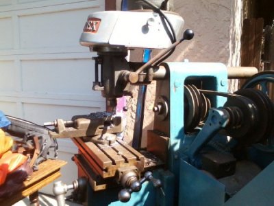
Hi Phil, I see you have a Rotex mill- how do you like it? I know they originally were in San Leandro in the 70s
Mark
 
Hi Phil, I see you have a Rotex mill- how do you like it? I know they originally were in San Leandro in the 70s
Mark

Hi Mark,

Rotex in San Leandro is apparently permanently closed. They were long out of the business of making mills.

My Rotex performs well, but it has a few maddening things I don't like. Since I have no DRO, I use the dials, which are 0.125" per turn. I want 0.100", or a DRO (but no easy way to mount for X axis). I do not use the horizontal mill part, but the vertical head works well enough, even if light in mass. The collets go up to 1/2" shank only. I like the that it is a knee mill, the vertical head tilts and nods, there are five belt speeds from 390 to 5200, a quill diameter of 2.18" and Z travel of 2". Table is about 5" x 20" and weighs 80 lbs. I think. Vise size is quite limited. I have a 3", but think a 4" might overhand back of table reducing Y travel. A friend and I estimate its weight at about 750 lbs. The friend used it and a Bridgeport and liked the Rotex better for small parts. Better feel he says. I would agree. I can send pics of it if you wish, or more info if you desire.


Phil
 
Hi Phil, I have a Diamond horizontal with a Rotex vertical head added. I've gotten a lot of use out of it. Surprised to hear about the 0.125" dials, that would mean 8 tpi leadscrews- wonder why they did that?
I like the Rotex head. Mine uses the Y style collets, I got a basic set with it then added some in between sizes. I don't have a lot of vertical knee travel so I have to plan my drilling operations carefully. I have a chuck with a 1/2" shank for small drill sizes.
Tools N' gizmos has those Y style collets if you need any replacements: www.tools-n-gizmos.com
Mark
0911161101-00.jpg
 
Hi Mark,

Yes, that is the Rotex head I have. Mine has rattle it on the middle speed. Mine has does not have the door yours has where the pulleys are. - Phil
 
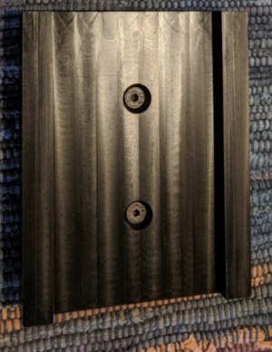
I am the original poster. Using some ideas mentioned here, I made my part. However, the result was unacceptable, leaving me wondering what I did wrong, and if it is even possible to make this part on my mill. Clearly, I screwed up somehow.

The machined part is 5" long and 4" wide and was about 0.560 thick. One side is machined flat. The other side (shown) is also flat, but a 5" x 3" x 0.267" deep slot is machined down the center. Two countersunk holes are in the middle, along the long axis, and are 2" apart. Variance in channel thickness was around 0.030"+, and varied along both X and Y axis. I removed it, cleaned everything, tightened the vice, etc., and resurfaced things.

Dimensions now are (thick section and channel)

Upper Left Corner: 0.5440 and 0.2760
Upper Right Corner: 0.5430 and 0.2750
Bottom Right Corner: 0.5465 and 0.2790
Bottom Left Corner: 0.5455 and 0.2795

.0035" variance on thick section, and 0.003" on channel. That is good enough, and thank goodness I could fix it!

1566859734619.png

My operations were:

1) Clamp 6" x 4.5" Delrin to table. Machine flat (except small areas under two clamps).
2) Place Delrin in bandsaw and cut off ends not machined that were under clamps. Delrin now has one flat side. Set Delrin aside.
3) Install and align vice to mill table. Clamp 2" x 5" (approx) piece of 1/4" aluminum in vice on parallels.
4) Machine aluminum flat.
5) Place Delrin on top of aluminum (still in vice) and clamp Delrin down using table clamps
6) Drill two holes through Delrin and aluminum. Countersink holes in Delrin. Remove Delrin. Thread holes in aluminum.
7) Put Delrin back on aluminum plate, install screws, clamping Delrin to aluminum plate.
8) Machine Delrin flat to a thickness of 0.560".
9) Machine 3" wide channel down 5" long axis of Delrin to a depth of 0.250.
10) Remove, deburr, measure. Thicknesses vary in center channel by over 0.030"...at least!!! ???

I do not understand what went wrong. Maybe my aluminum plate was too small for support. My cuts were shallow so no undue bending force applied to Delrin. No debris on Delrin or aluminum when mounting. ???

Asking since just trying to learn.

Phil
 
Phil, it looks like you are using a 1/2" end mill in many passes. In the pic you posted above (post #8) you used a facing mill. Is the facing mill still an option? It should divide those variances from multiple passes into a more even plane.
 
Back
Top