How to make two parts with close tolerances?

dansawyer

Registered
Registered
Joined
Jun 13, 2018
Messages
442
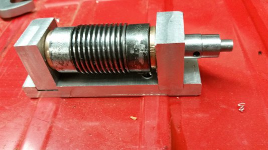
The attachment is a bearing cage for a worm gear. This did not work because I did not machine the holes in the 'ears' square. The part is made from a base and two 'ears' providing a bearing surface. I am planning to start over and so the question: . How to machine two 'identical' parts to close tolerances.
The tolerance surfaces on the bearing ears are: 1. the bottom and one end side need to be square and 2. the hole needs to a fixed distance from the corner in 1. above and be parallel to the end surfaces in 1 above. The other dimensions are not critical.
My thought was to machine in one pass. I would create a blank and clamp it to the mill bed. The process would be: 1. machine the two ends above, 2. identify the corner, measure off the hole center, drill the hole.
Is there a better way?
 

Attachments

  • worm_gear_cage.jpg
    worm_gear_cage.jpg
    4.8 MB · Views: 32
Last edited:
You are stacking more tolerances than you realize. It is not just the accuracy of the 2 blocks but also the accuracy of the base. You can make 2 perfect blocks but any error in the base will still be an error in the assembly.

Ideally, make the whole thing out of one piece.
If it must be multiple pieces, make the base and the blocks and assemble them together then finish machine it like it was one piece.

And if it really must be 3 seperat completely machined parts, then cut your tolerance in half for everything so the final stack up is still good. OR Design in some adjustability into the base so that you can align it during assembly.
 
It cannot be made from a single piece. The worm has 1/2 inch bearing ends and a 1 inch worm.
The original part allowed the end pieces to rotate on the base and used shims to fine tune the vertical alignment. I thought using slots in the base would remove the rotational componet of the end pieces. That design removes a dimension of precision from the base and leaves only one critical dimention in drilling, the angle of the hole to the vertical. Horozontal error can be removed by allowing the end piece to rotate on the base.
 
In this case, I would do as @Flyinfool recommended and wait to machine the bores to finish size until the end of the assembly. Assemble the components without the worm, then line bore. Disassemble and add the worm. You may still need to fiddle with alignment, but at least you know the bores are able to be true when assembled.

Designing a system for assembly, especially when parts are individually machined is a daunting task. In many cases, slots and other adjustment features are not practical (think of a car engine) and super tight tolerances are too expensive. In this case a functional approach of dimensioning and tolerancing for assembly and function must be done. This is called Geometric Dimensioning and Tolerancing (GD&T) and is an incredibly deep topic. The short story is, when done correctly, you provide the loosest tolerances to your manufacturers without sacrificing functionality. This may require your manufacturers to inspect their components in a functional manner rather than just reading dimensions off a print.

The entire field of metrology is based off of figuring out how to functionally measure components for both size and function so that a manufacturer knows they are shipping components that will assembly correctly when arriving at the end user.
 
"Drill" the hole! To avoid stacking tolerances, consider boring to final size as one block then cutting it in half. Drilling is always problematic for an accurate hole. You can get very accurate holes with a cheap boring head on a mill or a boring bar on a lathe. You can creep up on final.
Do you have a boring head? Reaming is another way of getting very accurate holes but a set of good reamers is expensive.
 
When I need to make parts like your vertical pieces, I've found machining them at the same time (bolted or clamped together), as a good way to insure the parts are identical. Taking your two vertical pieces and doing all the machining of them as if they were one. Drill them in one shot, as if they were one piece, mill the sides as if they were one piece. Etc.. That way when you separate them you know they are identical.

You could also take a block twice as thick as your two vertical pieces and do all your drilling and milling on it and then cut it in half. Looks like the side facing the worm is the only side that "needs" to be finished, so the cut edges could be facing outwards.

As for the base plate, as long as the material is flat and square to your milling table. Then cutting the slots to the same height should be pretty easy. Just make sure on the pass when you cut to the final depth, your quill is locked. Make the final cut on one slot. Move your table over to the other slot. Make your final cut on the second slot. Your slot heights should be close to identical.

Hope this helped?
 
Seems to me like the slots are overconstraining the blocks. With the worm assembled into the bocks, the orientations of the blocks are fixed in all but one axis (the worm axis). So don’t use a slot to further constrain the blocks. It is true that the bore through each block needs to be parallel to the bottom of the block and the same distance from the bottom of each block. The former will come from careful setup and the latter will come from machining them both together, as suggested above. Or using the fixed vise jaw as the reference and not moving the table between parts.
 
The hole is 5/8. I don't have a boring head that will go that small. I had thought about making one part, at doiuble thickness, and cutting it in half.
I am starting 'over' with fresh stock; I am cutting the base and vertical raw pieces.
I made a 3d CAD and printed a 3d model. Both frustrating and encouraing: the 3d model aligns quite well. I will use those dimensions to machine the next verstion.
Yes, I had concluded the slots added an unnecessary new critical dimension. I am not planning on using them. I had thought about adding a second locking screw the secure the end pieces from rotating.
 
Last edited:
The hole is 5/8. I don't have a boring head that will go that small. I had thought about making one part, at doiuble thickness, and cutting it in half.
I am starting 'over' with fresh stock; I am cutting the base and vertical raw pieces.
I made a 3d CAD and printed a 3d model. Both frustrating and encouraing: the 3d model aligns quite well. I will use those dimensions to machine the next verstion.

Your boring head should accept 1/2" shank tools. You can grind your own boring bar from and old endmill with a 1/2" shank or buy a cheap brazed cutter. These will bore nicely down to 3/8" or smaller.

Micro100 makes mini carbide boring bars with reducing sleeves that can bore down to 1/8" for $20 or so.

There are options, but I'm sure you can also make a drilled hole work if you can meet your precision requirement.
 
The hole is 5/8. I don't have a boring head that will go that small. I had thought about making one part, at doiuble thickness, and cutting it in half.
I am starting 'over' with fresh stock; I am cutting the base and vertical raw pieces.
I made a 3d CAD and printed a 3d model. Both frustrating and encouraing: the 3d model aligns quite well. I will use those dimensions to machine the next verstion.
5/8" reamer isn't too expensive, or get your best 5/8" drill ( I have drills with .0005" r/o), center drill, then 1/4", then 7/16", then your best drill that is close to .60". Finish with the 5/8" and it will be close to boring or reaming the hole. lubricate, clear chips.
 
Back
Top