

-
Welcome back Guest! Did you know you can mentor other members here at H-M? If not, please check out our Relaunch of Hobby Machinist Mentoring Program!
You are using an out of date browser. It may not display this or other websites correctly.
You should upgrade or use an alternative browser.
You should upgrade or use an alternative browser.
I need a pneumatic thingamabobby!
- Thread starter lesrhorer
- Start date
Well, the geometry is exactly as I designed it. I just did not realize there would be quite so much slop in the hinges. If the hinges were more precise, the current position would be fine. I did, after all, deign it to sit exactly as it sits now. I certainly knew the lid would be beyond its balance point: that was intentional. I just did not take into account the fact the sloppy hinges cause the lid to fall rather less than gently when the CG moves past vertical. I could alleviate the issue by buying better hinges, but moving the strut pin up 0.700" is easy, since two of the tapped holes are already there. This will set the opening angle to 65.2 degrees, instead of the original 85.0, which in turn will result in the CG of the lid to be just shy of vertical over the hinges (86.2 degrees).That's what I meant about being a PITA. Getting the length, force and geometry just right isn't easy with off the shelf struts.
I am also going to replace the mechanical latch with a magnetic latch. The current latch works, but it is not in the most convenient place. One also has to "fiddle" just a bit with the latch yoke to get it in place before closing the latch. While nowhere nearly as strong as the mechanical latch, whose cam action produces a huge mechanical advantage, a mechanical patch should be more than strong enough to keep the lid securely closed, and I won't have to get up and walk around the mill to get to the latch.
Last edited:
True, but I have a spare - the deal came with 2 struts, and buying another pair in a few years is hardly a daunting proposition. The existing force is a bit greater than necessary, of course, so it will take a while for the gas to leak out enough to render the strut useless. The lid has a weight of a bit less than 65N (15 lbs). Since it is symmetrical, the lifting force on one side is half that, or 32.5N when the lid is horizontal. (Half the weight is taken by the hinges.) The lid is 241 mm across, and the mobile strut pin is 100.2mm from the hinge point. When closed, however, the fixed strut pin is not directly over the mobile strut pin WRT the hinge plane. The actual angle between the hinge plane and the strut is 85.7 degrees, so this results in a mechanical advantage of sin(85.7) x 100.2 / 241, or 0.414. Thus, in order to lift the lid, the strut must produce 32.5/ 0.414 or 78.5N. The strut is rated at 120N, but that is the rated force required to compress the strut at full extension. This strut has a K-factor of about 1.2, so its force under full compression is around 140N, which is far more than enough to lift the lid at full compression, or even at full extension, for that matter. The actual compression is a little less than that (168mm vs 155mm), but still there is more than enough left over.The gas leaks off over time so the force changes.
That would mean something like almost half the gas must leak out before the strut will no longer be able to lift the lid when closed. Note, however, the strut will not be useless even at that point. While lifting the lid automatically is a nice feature, the main purpose of the strut is to hold the lid open, preventing it from closing or opening too much. By design, the lid is nearly balanced on the hinges when open, so the strut needs to supply almost no force at all to keep the lid open. If, after a few years, I have to give the lid a little bit of a help, I am not going to cry about it.
Crude sketch.I am not quote certain what you mean. Perhaps you might provide a drawing? If one draws a line from the hinge pin to the fixed strut pin, then in order to push the lid closed the moveable strut pin must be placed below the line. This cannot be accomplished if both strut pins are mounted directly on the mill head and mill lid, respectively. As far as I can see, in practical terms, this means mounting the fixed pin above the mill head using some sort of extension plate. No matter where this would be placed, the strut would be in the way. Here is the current mounting:
View attachment 473228
View attachment 473229
As mentioned above, I think I am going to move the upper strut pin up about 1/2", to prevent the lid from moving to the point where its center of mass is to the left of the hinge. This causes the lid to "flop" over against the strut limit rather aggressively. With the strut pin in the proposed position, the lid will always be applying a small compressive force on the strut, rather than trying to suddenly pull it apart.
Attachments
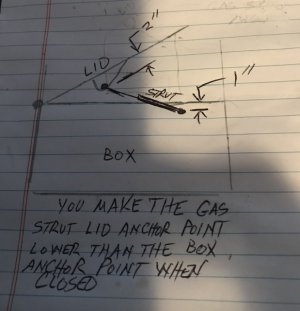
This is the way!Crude sketch.
In this case, it's not quite that simple. See the drawings below. The lid is placed right at the balance point in both drawings. Throughout its entire motion, the mobile strut pin must fit in the yellow area, although of course that area will move if I move the fixed strut pin. If I place the mobile strut pin below the fixed strut pin, the fixed strut pin must move far too the right and up, or else the lid will open far beyond the balance point, which is already an issue. Not only does this mean an extension plate will have to stick out so far to the right and up it will interfere with the switch and even the quill handle, but the mechanical advantage will fall so low the strut won't even be able to lift the lid. If I move the mobile pin back up where it was originally, then the mechanical advantage would be fine and I can move the fixed pin back to the left, but it would have to move way up, and then the strut would be in the way of accessing the drawbar and the pulleys. I just am not seeing any way I could make this work.


Last edited: