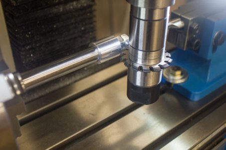
I want to cut my first gear

I found this website to use pins for measurement.

Using 0.125" pins (3.175mm), the distance over the pins is 1.023". I measure about 1.001" - 1.002". Somethings off!!!
Your link also has a calculator for blank diameter and comes up with 0.8858, same as what you have. Can you measure the root diameter, should be 0.6644" for a correctly made gear.
 
The best I can measure, the root diameter is about 0.654".
 
It does look like something is a little off, but you didn't go far enough to answer the most important question. The final tooth is the most critical part of cutting gears. If it's skinny or fat, you screwed up. One of my first gears looked like an escape wheel.

Here.

1662533737676.png
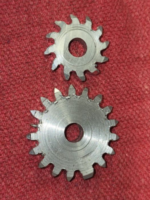
On the top one, I didn't set the Z axis correctly. I got a gear-like object, but the teeth were off by half of the width of the cutter.
On the bottom one, I made a dividing head cranking error that resulted in a skinny tooth, and ultimately a fat tooth.

Until you go all the way around, it's hard to say what went wrong where. Your teeth to this point look good. A little pointy. Maybe you're cutting in too far. But the real question is will the gear work? The first gears made by humans were hand filed and kind of crappy, but they functioned.

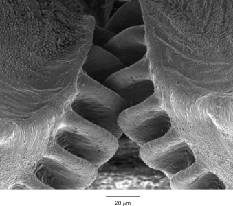
It takes Mother Nature and/or God to make perfect gears, such as those on the planthopper (Photo courtesy of LiveScience):
1662534092115.png
I say just run with it, make your gear, pointy teeth and all, and see if it runs. It will probably run as long as all the teeth are even. You can obsess yourself right into oblivion in this hobby if you let yourself.
 
Last edited:
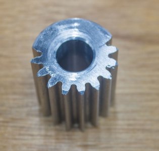
I never finished cutting the gear when things looked awry. I went around more than half way so I could measure the root diameter and the distance over wires.

So, looking at this more closely:

root diameter = OD - 2*(whole depth) = 22.5mm - 2*(2.8125mm) = 16.875mm
or
root diameter = OD - 2*(whole depth) = 0.866" - 2*(0.111") = 0.644"

Since I measured the root diameter as 0.654", I must have went in too far. How? I don't know. I carefully touched off on the side of the gear blank with the gear cutter running. I just kissed it. Then, I used my mill to move in 0.111".

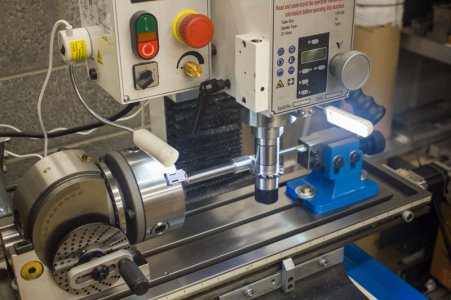
Unless my mandrel flexed and the gear blank got pulled into the cutter? I made the 8" long mandrel out of 12L14 steel with 5/8" diameter at one end (into dividing head chuck) and threaded 3/8" on the other to hold the gear blank.

I may try again today and just cut on opposite sides of the gear blank (for quick measurement) and keep taking cuts until the root diameter and distance over wire is right.

This is quite the mystery.

IMG_6227.jpg
 
I found this website to use pins for measurement.

Using 0.125" pins (3.175mm), the distance over the pins is 1.023". I measure about 1.001" - 1.002". Somethings off!!!
For a 20 degree pressure angle, your measurement over 1/8” pins should be 1.015, I think you put a 14.5 degree pressure angle in the calculator to get 1.023”.

That last picture is much better then what the first one looked like. That looks like the proper form, just maybe a little too deep. If you go too deep, the tip will get thinner, so that might be your issue. Maybe try another gear and go in steps instead of full depth the first pass and see if you get something that measures right.
 
For a 20 degree pressure angle, your measurement over 1/8” pins should be 1.015, I think you put a 14.5 degree pressure angle in the calculator to get 1.023”.

I get 1.0235" for N=16, module=1.25, PA=20, pin diameter=3.175mm (0.125"). See below.

Inputs
Number of Teeth: 16
Gear Type: External
Module: 1.25
Pressure Angle: 20 degrees
Pin Diameter: 3.1750 mm
Profile Shift Coefficient: 0

Outputs
Measurement over Pins: 25.9970 mm 1.0235 in
Minimum Pin Size: 2.0222 mm 0.0796 in
Pin Size on Pitch Line: 2.1742 mm 0.0856 in
Maximum Pin Size: 4.5094 mm 0.1775 in
Pitch Diameter: 20.0000 mm 0.7874 in
Profile Shift: 0.0000 mm 0.0000 in
 
That looks a lot like a Grizzly g0704.

I have no idea if it's actually contributing to your problems, but after reading through a bunch of clock making books, I totally changed my goals for my own setup. The 3-jaw "you get a center, but maybe not the center you want" scroll chuck is gone, replaced by a MT2 ER32 collet chuck in the dividing head. I'm no longer using the tailstock at all. I haven't actually fabricated it yet, but I'm going to copy a blank holder from the "Huckabee wheel making fixture" from "Building an American Clock Movement" by Steven G. Conover, and size the the shank to fit one of my ER32 collets. Call it 0.750".
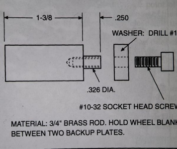
1662547795362.png
What did Mr. Huckabee get right that I did wrong? He realized the threaded connections are the enemy of concentricity. The gear blank in this diagram registers on the 0.326" diameter that sticks out of the chuck/collet. The blanks clamp through the #10-32 threads, with the aid of the washer. Varying widths of blanks, and/or stiffening plates are accommodated, and everything will turn out concentric, because the threads aren't relevant to the concentricity of anything.

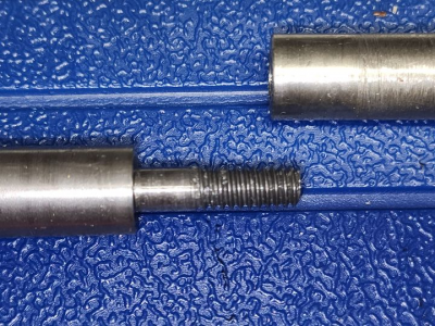
This is hugely different from the gear cutting arbor I made, which put the threads and the registration diameter on a rod that screwed into the left portion. Left and right rods were the same tool steel blank, the hole was reamed, but with this nonsense clamped between the 3-jaw scroll chuck on my dividing head and a tailstock, my parts basically stood no chance of coming out totally concentric.

When I redo this setup in the near future, I'm going to make a fixture that clamps into the ER32 on my dividing head, and has no tailstock support at all. This should be totally fine for 0.0625" clock wheel blanks, although you should probably devise a setup that involves tailstock support, because your pinion is relatively long.

My fail arbor:
1662550350456.png
 
For a 20 degree pressure angle, your measurement over 1/8” pins should be 1.015, I think you put a 14.5 degree pressure angle in the calculator to get 1.023”.

That last picture is much better then what the first one looked like. That looks like the proper form, just maybe a little too deep. If you go too deep, the tip will get thinner, so that might be your issue. Maybe try another gear and go in steps instead of full depth the first pass and see if you get something that measures right.
Could be the website calculator. I got the same numbers as @devils4ever .

The cut off gear looks a lot better than the earlier picture. I think the teeth were cut a little deep. The root circle is 0.01" too small. Since the cutter widens near the base a tiny displacement in depth will make a large change in tip width. Try again. Do go all the way around, because that's what counts.
 
I get 1.0235" for N=16, module=1.25, PA=20, pin diameter=3.175mm (0.125"). See below.

Inputs
Number of Teeth: 16
Gear Type: External
Module: 1.25
Pressure Angle: 20 degrees
Pin Diameter: 3.1750 mm
Profile Shift Coefficient: 0

Outputs
Measurement over Pins: 25.9970 mm 1.0235 in
Minimum Pin Size: 2.0222 mm 0.0796 in
Pin Size on Pitch Line: 2.1742 mm 0.0856 in
Maximum Pin Size: 4.5094 mm 0.1775 in
Pitch Diameter: 20.0000 mm 0.7874 in
Profile Shift: 0.0000 mm 0.0000 in
Looks like I made a typo when converting the 1/8” to metric and was off by 0.075 on the pin diameter when I did it, but interesting enough, switching to 14.5 degree angle in the calculator gave almost exactly the correct number.
 
Back
Top