Ideas for proving DRO calibration

On newish lathes and mills you can use the dials to see if there is cumulative error and how well they track. I have checked a number of DRO scales against 123 and 246 blocks as well as use them to check the electronic calibration of electronic edge finders, I have yet to find one that wasn't in spec. These type of measurements if one stacks a series of blocks may lead to more error than inherent in the scales, but in some cases the scale resolution/parameters are not set correct. There are also calculation errors due to rounding errors based on the DRO software and scale resolution. I did have a problem on my previous mill that I was always off on what the dials indicated vs. the cut, when I measured the dial accuracy I found that "I go 10 turns on the X axis (1.200") I get a readout on the DRO of 1.1808", and on the Y axis I get 1.1782" for the same 10 turns. It is reproducible at various points in the travel. So a discrepancy of about ~0.02" per 10 turns". Evidently the manufacturer (Optimum BF30) of the mill at the time used metric leadscrews with imperial dials, all of which were useless for any type of accurate work. It was also never corrected under warranty, so without the DRO you had a fancy drill press.
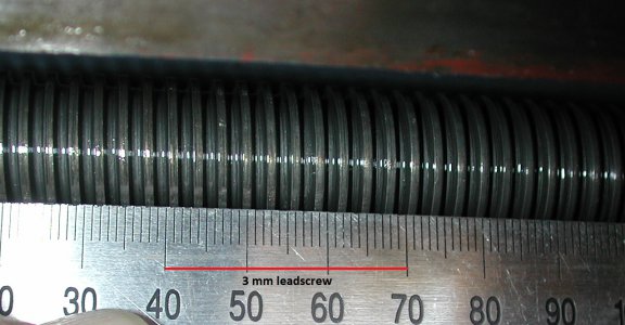
BF30 leadscrew.jpg

My point is I would use whatever you choose to verify the accuracy of the DRO scales, but I would be hesitant to calibrate them over the full travel distance unless you have the equipment to do it accurately. On a 5μm (0.0005”) scale you would need measurement blocks and/or a system that exceeds this accuracy to calibrate it. If you feel the scale is not preforming accurately than I would contact the manufacturer.
 
On newish lathes and mills you can use the dials to see if there is cumulative error and how well they track. I have checked a number of DRO scales against 123 and 246 blocks as well as use them to check the electronic calibration of electronic edge finders, I have yet to find one that wasn't in spec. These type of measurements if one stacks a series of blocks may lead to more error than inherent in the scales, but in some cases the scale resolution/parameters are not set correct. There are also calculation errors due to rounding errors based on the DRO software and scale resolution. I did have a problem on my previous mill that I was always off on what the dials indicated vs. the cut, when I measured the dial accuracy I found that "I go 10 turns on the X axis (1.200") I get a readout on the DRO of 1.1808", and on the Y axis I get 1.1782" for the same 10 turns. It is reproducible at various points in the travel. So a discrepancy of about ~0.02" per 10 turns". Evidently the manufacturer (Optimum BF30) of the mill at the time used metric leadscrews with imperial dials, all of which were useless for any type of accurate work. It was also never corrected under warranty, so without the DRO you had a fancy drill press.

View attachment 317037

My point is I would use whatever you choose to verify the accuracy of the DRO scales, but I would be hesitant to calibrate them over the full travel distance unless you have the equipment to do it accurately. On a 5μm (0.0005”) scale you would need measurement blocks and/or a system that exceeds this accuracy to calibrate it. If you feel the scale is not preforming accurately than I would contact the manufacturer.
It sounds like you have metric leads screw which approximate inch measure. If your lead screw has a pitch of 3mm, you would traverse 30mm in ten revs. or 1.1811". I have a similar problem which was one reason for adding a DRO.
 
My recently acquired LC-30A mill has a hybrid approach.
The marking says |-| = .0254” but the actual graduations are .001.
Smart folk here reminded me that 1 cm x 2.54= 1 in.
Doh!


Sent from my iPhone using Tapatalk
 
You can just start out by comparing their overall accuracy to the dials on the lathe. Take out any play in the dial, zero it and the DRO and then compare to the DRO over each turn, and over something like 10 turns. This will tell you incremental and overall travel information in relation to the dials. If they compare then good enough.
That's what I did.
 
I am installing a nifty Chinese DRO and set of glass scales on my grizzly 12x36. I am done , except the z axis chip shield. I am pausing here to check the accuracy of the set up, as I am running out of time to complain if there is a problem. I don't need a chip shield to test these, so it can wait. Currently I have a one inch standard used to calibrate micrometers and such. I have no Jo blocks. I have an er40 collet chuck mounted to the spindle with a nice ground flat face on it. It's the kind that came as a plate with an er40 chuck protruding from it, around the chuck is the ground flat. I have .0001 Interapid test indicator on a mag based noga arm. I have an Aloris knockoff qctp on the compound or I could also attach a vertical milling slide in place of the compound. I'm hoping to use this gear (preferably without making parts) to check the cross slide and carriage scales against the 1" standard. Something like hold the standard in a repeatable fashion against the chuck face and bring the indicator in till preloaded and zero it as well as the dro. Then remove the standard, bring the indicator in until it again reads zero and check the readout. I'm hoping to pick other peoples brains for solutions to holding the standard, indicator and general set up. Thanks for making my puzzle your puzzle.
how about a gage rod-here's one thats not too expensive: https://www.ebay.com/sch/tvwtool/m.html?item=253681296790&ssPageName=STRK:MEBIDX:IT&rt=nc&_trksid=p2047675.l2562 . scroll down to lufkin 15" rod
 
ok, let's see, lot's of responses. Thanks. As stated my time is running out, and I have no Jo blocks. So I can't use Jo blocks or order tools in time. I got high resolution scales and wish to test better than with my igaging scales, handwheels, calipers, ect. My z axis handwheel measures to .010" per division, which has never been handy . I don't know what my 123 blocks measure, but I used them. My good calipers say 3.000 and they read down to .0005. So if I trust them one more digit than I should ( and I do) the blocks are between 3.0004 and 2.9996 or so. The Z reads 3.0002" pretty reliably. I'm figuring that's not too bad, not knowing my blocks. That set up was good and solid though. The x setup not so solid and tests didn't repeat well. The results I got varied, but showed from abt.0005 to .0015. I'm going to get a metric bolt tomorrow so I can replace the apron fill screw with said bolt and use my mill clamp set to secure a 123 block to the way. Then we'll see about more trustworthy readings.
 
I hope my ways aren't bad enough to give me issues. There is little wear. As for screws I don't understand how they would cause issue. I got linear scales, not rotary encoders, so I don't know how they would affect my scales/readout. Somebody might have to educate me there.
 
My hopes are that tomorrow I can achieve results in the x similar to those I got in the z. If so, no complaining for me. I should have had something here ready and waiting to test them out when they arrived. Oops. Shame on me.
 
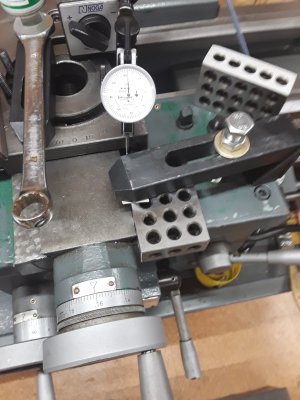
This is what I came up with. I bought 2 metric bolts to cobble together into 1 that was long enough for the job. I pulled the apron fill plug and used the metric cobbled bolt in its place. Then I could use my toe clamp to secure the 123. Once I got that to happen I achieved the same results in X axis as with the Z. I thought that was pretty promising. This evenings test along with your experiences reassures me about keeping them, no complaints. I look forward to finishing this install so I can test drive the new set up. Thanks for all the help and ideas. 20200318_200023.jpg
 
Back
Top