- Joined
- Jan 16, 2020
- Messages
- 8
I recently purchased a set of iGaging Absolute DROs for my Clausing 8520 mill. I had them on hand for a few weeks before I got the chance to install them, and now, a couple of weeks later yet, I am posting photos of how I installed them.
Keep in mind that the photos are of my initial installation, and I plan to make better spacers, as well as one read head plate where I made a hole in the wrong place. My apologies for not cleaning up my mill before taking the photos, but I took them immediately after I completed the installation, with only basic cleaning being done before taking the photos.
I started with the X readout, which required a 24" rail. The X travel on this mill is only 15.125", but with the table being 24" long, I still had to cut the rail down to an appropriate length. The X axis was the only rail that I had to trim, and it was easily accomplished with a flex shaft tool and a small cutoff wheel. By mounting the rail with the plastic strip facing out, and the cable from the read head sticking up, and the origin set to zero when the table is all the way to the right, the numbers will climb as the table is moved to the left. In order to leave room behind the rail so that the read head could be mounted to the existing stop block, 1/2" thick spacers were placed between the rail and the table.
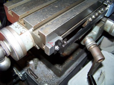
A simple piece of 1/8" x 1/2" flat stock was used to mount the read head to the stop block.
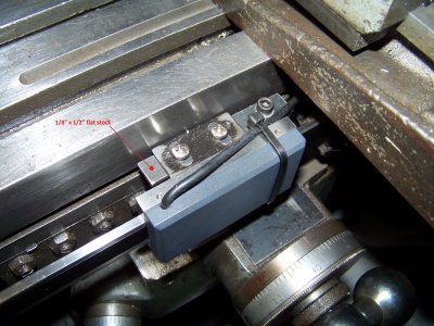
Y travel on this mill is only 5.125" and it was done next, using a 6" DRO with the rail flipped over so that the plastic strip is facing the knee, and the cable exiting the bottom of the read head. When the table is moved as far as possible away from the column, and the origin is set to zero, the numbers will climb as the table is moved toward the column. This may seem backwards to some, but it works well for me. I put spacers 5/16" thick between the knee and the rail. This allowed the read head to mount to the side of the saddle with a simple flat plate. The one in the photo is missing a screw. For some silly reason I drilled the two bottom holes the same distance apart as the top ones. Oops. Gotta make that plate over again.
Here is the rail mounting for the Y axis.
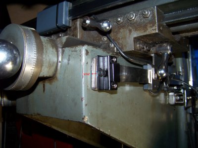
And the read head mounting.
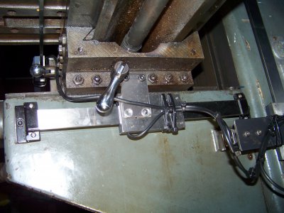
The Z axis travels 11.625", and a 12" DRO did the trick here. This is the one I dreaded the most due to the sloping shape of the side of the column, but this proved to be quite easy to get around, but it took some time. The bottom of the rail was mounted at the height shown in the photo, with the mounting screw at about the same elevation as the bottom part of the "G" in Clausing. This position was determined in sort of a by guess and by gosh method, based on where the read head was mounted. I chose to mount the read head to the existing holes on the side of the knee. This allowed enough clearance for the Y axis read head to pass, and also allowed access to the oiler for the knee gibs without giving the DRO a bath in oil. There is a spacer 1.25" thick between the knee and the plate that mounts the read head. This spacer was made partially from 3/4" square tubing, which allowed for mounting the tube to the knee, then the remaining spacers and the read head bracket were fastened to the square tube. The rail was mounted with the plastic strip facing the knee, with the cable exiting from the rear of the read head. If the knee is placed at the bottom, and the origin is set to zero, the numbers will climb as the knee is raised. The bottom end of the rail has no spacers, but the top of the rail has a spacer 0.750" thick.
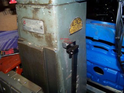
Z axis upper rail mount
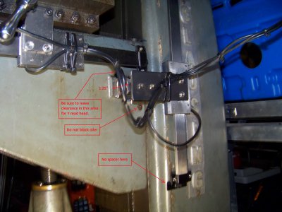
Z axis read head and lower rail mounts
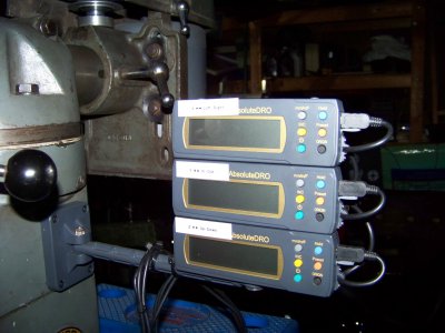
Last but not least, I mounted the readouts to the right side of the column and placed ID stickers on them. My one son and his daughter are learning how to use the mill, so simply putting X,Y, and Z on them was not going to be enough. A quick explanation of what X. Y, and Z are is included.
This entire project was completed in about six hours from start to finish, so it was not all that bad! I still need to mount a piece of aluminum angle to the front of the table to cover the head and rail for the X axis, and I should do something for the Y axis also, but for now I am happy just to have them mounted and usable!


Keep in mind that the photos are of my initial installation, and I plan to make better spacers, as well as one read head plate where I made a hole in the wrong place. My apologies for not cleaning up my mill before taking the photos, but I took them immediately after I completed the installation, with only basic cleaning being done before taking the photos.
I started with the X readout, which required a 24" rail. The X travel on this mill is only 15.125", but with the table being 24" long, I still had to cut the rail down to an appropriate length. The X axis was the only rail that I had to trim, and it was easily accomplished with a flex shaft tool and a small cutoff wheel. By mounting the rail with the plastic strip facing out, and the cable from the read head sticking up, and the origin set to zero when the table is all the way to the right, the numbers will climb as the table is moved to the left. In order to leave room behind the rail so that the read head could be mounted to the existing stop block, 1/2" thick spacers were placed between the rail and the table.

A simple piece of 1/8" x 1/2" flat stock was used to mount the read head to the stop block.

Y travel on this mill is only 5.125" and it was done next, using a 6" DRO with the rail flipped over so that the plastic strip is facing the knee, and the cable exiting the bottom of the read head. When the table is moved as far as possible away from the column, and the origin is set to zero, the numbers will climb as the table is moved toward the column. This may seem backwards to some, but it works well for me. I put spacers 5/16" thick between the knee and the rail. This allowed the read head to mount to the side of the saddle with a simple flat plate. The one in the photo is missing a screw. For some silly reason I drilled the two bottom holes the same distance apart as the top ones. Oops. Gotta make that plate over again.
Here is the rail mounting for the Y axis.

And the read head mounting.

The Z axis travels 11.625", and a 12" DRO did the trick here. This is the one I dreaded the most due to the sloping shape of the side of the column, but this proved to be quite easy to get around, but it took some time. The bottom of the rail was mounted at the height shown in the photo, with the mounting screw at about the same elevation as the bottom part of the "G" in Clausing. This position was determined in sort of a by guess and by gosh method, based on where the read head was mounted. I chose to mount the read head to the existing holes on the side of the knee. This allowed enough clearance for the Y axis read head to pass, and also allowed access to the oiler for the knee gibs without giving the DRO a bath in oil. There is a spacer 1.25" thick between the knee and the plate that mounts the read head. This spacer was made partially from 3/4" square tubing, which allowed for mounting the tube to the knee, then the remaining spacers and the read head bracket were fastened to the square tube. The rail was mounted with the plastic strip facing the knee, with the cable exiting from the rear of the read head. If the knee is placed at the bottom, and the origin is set to zero, the numbers will climb as the knee is raised. The bottom end of the rail has no spacers, but the top of the rail has a spacer 0.750" thick.
Z axis upper rail mount

Z axis read head and lower rail mounts

Last but not least, I mounted the readouts to the right side of the column and placed ID stickers on them. My one son and his daughter are learning how to use the mill, so simply putting X,Y, and Z on them was not going to be enough. A quick explanation of what X. Y, and Z are is included.

This entire project was completed in about six hours from start to finish, so it was not all that bad! I still need to mount a piece of aluminum angle to the front of the table to cover the head and rail for the X axis, and I should do something for the Y axis also, but for now I am happy just to have them mounted and usable!


