Input needed on my wireless DRO project

ycroosh

Active User
H-M Supporter - Commercial Member
Joined
Apr 4, 2013
Messages
691
Good part of the day,
I'd like to peek your brains about my little DRO project. (details here: http://www.yuriystoys.com/p/android-dro.html )
I'm working on the next set of features and want to make sure they are done the way that would make them usable for other people.
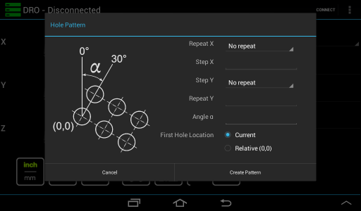
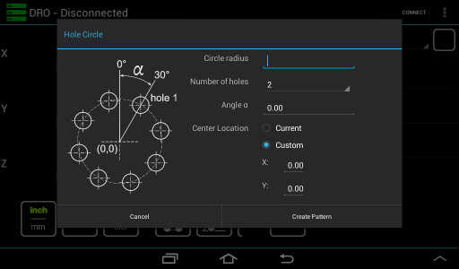
The two attached screenshots show hole circle and hole pattern functions. Does the layout make sense? Is there something missing?
The third functions (or possibly third and fourth) is tool offset/locate edge. That one I haven't figured out how to do in a way that avoid screw-ups.

I would really appreciate some input, especially form the people who built or are thinking about building one of these in future.

Thank you in advance
Yuriy

P.S. By the way, if you have suggestions for other functions - please let me know....
device-2013-07-16-175645.pngdevice-2013-07-16-175704.png

device-2013-07-16-175645.png device-2013-07-16-175704.png
 
Looking at the two displays I'm gathering that you'd use them to give you an X-Y coordinate for a hole pattern, correct? If that's the case (and given the displays are touch screens) would you just touch the particular hole that you wanted and it will give you coordinates?

Another thing that would be a useful feature for me (and anyone with a variable speed lathe like mine or a VFD) would be an option to display rpm (with proper hardware, of course).

Edit: Thought I'd let you know the app seems to run beautifully on my Nook HD+ in case you hadn't tried one of those. Looking at EBay they're running ~$140... with a nice 9" screen.
 
Looking good so far. L plan on building one when you get the USB version out. I have a 10" tablet with no blue tooth.


I can post an accu-rite manuel If you would like to see how thay do things
 
Yuriy,
I don't have any input for you, but I just wanted to say that I think what you've done looks great. I am definitely planning on putting one together, but it's not likely to be for a couple of months. Again, just wanted to say THANK YOU! for what you've done...
 
Looking at the two displays I'm gathering that you'd use them to give you an X-Y coordinate for a hole pattern, correct? If that's the case (and given the displays are touch screens) would you just touch the particular hole that you wanted and it will give you coordinates?

Another thing that would be a useful feature for me (and anyone with a variable speed lathe like mine or a VFD) would be an option to display rpm (with proper hardware, of course).

Edit: Thought I'd let you know the app seems to run beautifully on my Nook HD+ in case you hadn't tried one of those. Looking at EBay they're running ~$140... with a nice 9" screen.
Rennkafer,
I'm not yet at the point where I can display "real" hole pattern (the image on the left is a graphic I've made to illustrate the feature). The version I'm working on will create the pattern (once a user enters the parameters) and add it to the selected workspace as a list of holes. You would then be able to select any hole from the list on the right of the DRO etc.

I have a lathe that will be using a VFD once I get a chance to add 220V outlet in my garage. Tachometer is definitely on the short list. I added the provisions for tachometer input to the communication protocol and the new board has two pins reserved for it. Still trying to figure out the UI (I've made a LOT of changes in the upcoming version to make user-configurable layouts possible but I don't think I will get there in the next few months.

Thank you
Yuriy
 
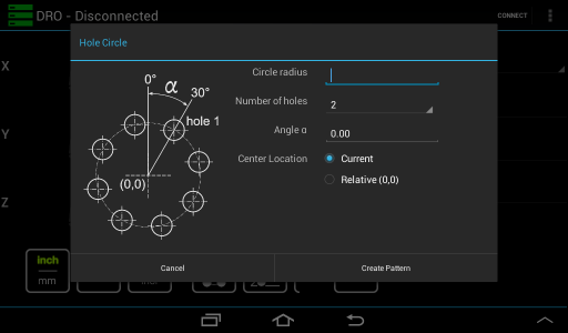
The only thing that I would suggest, which has not already been suggested, is to change the wording of how you refer to the starting point of the arrays. You are currently saying "Current" and "Relative". If I am understanding correctly, "Relative" uses the current X and Y zeroes as the starting point for the array.

I feel that it would be more correct to say "Absolute", instead of "Relative", and the "Current" position would become "Relative", as in relative to your current position.

I realize this is minor and somewhat picky, but I feel it would make more sense, and is more technically correct.

I could also see use in being able to specify a set of starting coordinates. Yes, I realize that you could just move to the desired position and use the "Relative" (what I would call relative) option.

Just my 2 cents, and it looks GREAT btw!

-Cody

The idea was to either center the circle around the current position (whatever it might be) or the point currently set to be (0,0). The 0,0 would likely be the zero point in relative mode, though. Take a look at the screenshot below. I left "Current" intact but replaced the "relative" option with a set of user-provided coordinates. If left intact it will be 0,0 but can be changed to any other coordinate.

Thank you
Yuriy


device-2013-07-16-232325.png

- - - Updated - - -

Yuriy,
I don't have any input for you, but I just wanted to say that I think what you've done looks great. I am definitely planning on putting one together, but it's not likely to be for a couple of months. Again, just wanted to say THANK YOU! for what you've done...

Thank you for the compliment. I'm glad that the project is turning out to be useful to the community :)

- - - Updated - - -

Looking good so far. L plan on building one when you get the USB version out. I have a 10" tablet with no blue tooth.


I can post an accu-rite manuel If you would like to see how thay do things

A manual would be great. That way I can try to stick to "industry standards" a bit more.

As far as the USB version goes... I got it working to a degree but its still pretty clanky. I'm hoping to include it in the upcoming version but I'm not certain I can make it stable enough.

Thank you
Yuriy

device-2013-07-16-232325.png
 
Here is the DRO200m manuel
 

Attachments

  • DRO200Mmanual.pdf
    248.2 KB · Views: 33
looks good!

I would second the use of "Absolute" and "Relative" terms as those are standard terms used in the industry and could cause confusion if used differently.

other useful feature that I like is the 1/2 feature. (find middle of part/measurement) -should be fairly simple to implement (just halve the axis value)

The 1/2 feature is already there. You get to it by long-pressing the axis display. Look in the middle of this post: http://www.yuriystoys.com/2013/02/new-version-of-android-dro-coming.html

Here is where I'm a bit confused with Absolute/Relative: there are three kinds of position I keep track of. The "real" absolute which is dictated by the encoders; the "datum" position (i.e. work space origin point) and the "incremental" or "relative" position. I don't think many people would use the "absolute zero" point for the hole circle center, so if a "zero" is used it would be the relative/incremental zero point. (unless relative and incremental are two different concepts and I'm mixing them together erroneously).
I would imagine three scenarios:
1. I want to create a circle around the current zero point
2. I want to create a circle around the position I'm at right now
3. (as suggested below) I wan to create a circle around an arbitrary point somewhere else.

Would it make sense to call those cases:

Center Location
1. Current zero
2. Current point
3. Custom coordinate

Thank you
Yuriy

P.S. This is one of the reasons so many user interfaces suck: programmers design them for themselves, so your collective input is very much appreciated :)
 
Back
Top