It's the Little Things

Funny you should ask. Randy didn't actually provide the numbers in his video, he just used an insert to establish the cut and tap locations.

That's not my style, so I drew it up in Acad and interrogated for the dimensions. This is the smaller one.

View attachment 413593

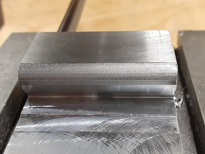
The lathe work is pretty obvious, here's the setup for milling the insert seat.

View attachment 413594

I need to do a little work on the drawing for the larger one.
That's not my style, so I drew it up in Acad and interrogated for the dimensions. This is the smaller one.
So, it looks like you were able to cop-out Randy for those dimensions with your mad skills! :grin: Sorry, I couldn't resist!
 
I tested the small cutter today and found I needed more clearance behind the cutting edges. I was able to take some material off the end and taper to get it. Screwed up my nice oxide job. I've updated the drawing to reflect the changes (both in this post and the original). I also biased the tapped hole a couple of thousandths toward the back of the insert seat to apply a little pressure there.

Drawing Removed

The larger cutter should already have enough clearance, but I won't know for sure until I have the inserts.
 
Last edited:
Funny you should ask. Randy didn't actually provide the numbers in his video, he just used an insert to establish the cut and tap locations.

That's not my style, so I drew it up in Acad and interrogated for the dimensions. This is the smaller one.

View attachment 413645

The lathe work is pretty obvious, here's the setup for milling the insert seat.

View attachment 413594

I need to do a little work on the drawing for the larger one.
This is the part I wasn’t sure how to set up.
I was struggling with the placement on of the hold down screw. Your mill set up and the DRO, .123” offset should do the trick.
I think i’m going to give this a try.
Thanks for the pic of your milling set up.
 
Last edited:
I saw a nice method and used it to make a couple of these, and it makes things way easier and more accurate. Rather than use calculated dimensions for the screw hole, use a pin just the size or slightly larger than the insert mounting hole. Chuck up the pin, put the insert on the dovetail roughly where it would sit, lower the pin to/through the insert hole and move the Table around in X and Y until the insert is exactly where it should be. Drill and tap there, or move the hole position a couple thousandths to crowd the insert for a tighter fit.

Edit: Ha ha, maybe it was Randy’s tip. The sign of a very experienced machinist is when you can’t remember who you learned something from. :)
 
I tested the small cutter today and found I needed more clearance behind the cutting edges. I was able to take some material off the end and taper to get it. Screwed up my nice oxide job. I've updated the drawing to reflect the changes (both in this post and the original). I also biased the tapped hole a couple of thousandths toward the back of the insert seat to apply a little pressure there.

View attachment 413646

The larger cutter should already have enough clearance, but I won't know for sure until I have the inserts.
How far down did you cut to seat the insert?
 
I tested the small cutter today and found I needed more clearance behind the cutting edges. I was able to take some material off the end and taper to get it. Screwed up my nice oxide job. I've updated the drawing to reflect the changes (both in this post and the original). I also biased the tapped hole a couple of thousandths toward the back of the insert seat to apply a little pressure there.

View attachment 413646

The larger cutter should already have enough clearance, but I won't know for sure until I have the inserts.
Looking at this drawing it looks the same as the other drawing you posted earlier.
 
Looking at this drawing it looks the same as the other drawing you posted earlier.
The dimension to the back of the insert seat was increased to move the insert farther out. I updated the earlier post so there won't be an incorrect version to be mistakenly used.

How far down did you cut to seat the insert?
In each one, the seat is cut an amount equal to the insert thickness below centerline, which puts the cutting edge on center. It's shown in the end view to the right.
 
The dimension to the back of the insert seat was increased to move the insert farther out. I updated the earlier post so there won't be an incorrect version to be mistakenly used.


In each one, the seat is cut an amount equal to the insert thickness below centerline, which puts the cutting edge on center. It's shown in the end view to the right.
Yup stupid me was looking at it the wrong way
 
I got to do a little work with the small cutter yesterday. Running at 1320 rpm it leaves a very nice finish.

20220716_112218.jpg
 
Today I started noticing some problems with the little cutter. There were signs of rubbing on the clearance angle behind the cutting edge, and the bottom of the insert (surface against the cutter) was breaking down. The inserts had arrived for the larger cutter so I loaded it up. By the time I finished the first pass it was showing the same kind of breakdown, only worse. At first I was thinking that the clearance angle of the insert was not sufficient for the radius of the cutter, but that didn't make much sense. Then I measured the thickness of the inserts. The little one is supposed to be .093, but it measures .103. Same thing for the large insert, .166 instead of .156. This puts the cutting edge "above" center, like a parting tool that is too high.

I intend to remake the little cutter, which is pretty beat up. I may be able to repair the big one. If not, I will remake it too. Will be removing the drawings above until I have this worked out.

It's a shame, they LOOKED so good.
 
Back
Top