Lathe Spindle Indexing

8ntsane

Active User
Registered
Joined
Dec 1, 2010
Messages
1,172
Hi Guys

I have added a new addition to my lathe for doing simple indexing. I allready have a set up for the LH end of the spindle, that takes a expanding spindle plug, and dividing plates, but wanted something thats easy, and fast to use. In my crowded work area, its not allways easy to get to the LH end of my machine, and the time to get it all set up to use it. If it takes to long, I might as well just take the job over to the mill and do it there. I dont enjoy tearing down a setup to do the next operation, and some times the mill allready has a in progress job still in it.

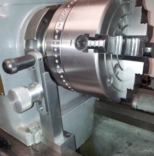
My Spindle is a L-1 type, and most all of my chucks are mounted up with a adapter plate as shown in these pics. This plate has be drilled,milled,and chamfered for 60 holes, at 6 degree spacing. With 60 holes, it gives me the most divisions that I most commonly use. It will do 2,3,4,5,6,10,12,15,20,30,60 divisions.

Though this wont cover everything, it does common used divisions like 3,4,5,6,10,12 For many jobs this will speed up the process of putting in a say , a 5 bolt pattern in a part, without taking it out of the lathe chuck, and heading over to the mill. My tool post driller will get much more use with this addition. Bolt circles of the available divisions will be completed on the lathe. For the other divisions that this 60 hole job wont do, I still have the set up for the LH end that uses dividing plates, and some times gears.

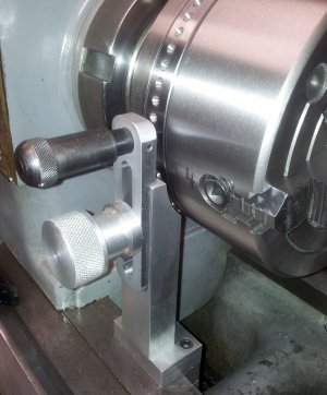
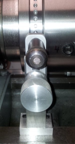
Anyway here,s a few pics. The spring loaded handle shown, a part used on my rotary table for dividing with plates, will have a mount that clamps to the flat way directly in front of the chuck, That will have vertical ajustment to centre up the pin to lock the position.


I did this on the 8 inch 4-jaw chuck adaper plate, as I use the 4-jaw most.
20130328_121645 (2).jpg 20130328_121705 (2).jpg 20130328_121129 (2).jpg
 
Last edited:
Hi Guys

Here is the finished spindle lock I made for the Sidney Lathe.
Its just a way mounted rig that mounts the crank handle from my 12 inch rotary table. The handle fits in the up right in a .200 deep slot. This should keep it steady, and will allow for vertical ajustment.

Other than drilling and tapping the hole in the vertical upright in the centre of the slot, to lock the crank handle in place, she,s pretty much done. Here.s a couple of pics.

2012-03-04191156.jpg

2012-03-04191141.jpg

2012-03-04190913.jpg

2012-03-04190856.jpg

All bits and pieces for this project are as usual, outta the scrap bin!

2012-03-04191156.jpg

2012-03-04191156.jpg

2012-03-04191141.jpg

2012-03-04191141.jpg

2012-03-04190913.jpg

2012-03-04190913.jpg

2012-03-04190856.jpg

2012-03-04190856.jpg
 
Paul, thats a fantastic job. What did you use for indexing the hole layout?
I notice in this pic that the holes that have been drilled near the scribe marks, (about 9 and 11o'clock) are not positioned the same. Is that an error in the markout or in the drilling or just of no consequence?


Cheers Phil

2012-02-29145802.jpg

2012-02-29145802.jpg
 
Paul, thats a fantastic job. What did you use for indexing the hole layout?
I notice in this pic that the holes that have been drilled near the scribe marks, (about 9 and 11o'clock) are not positioned the same. Is that an error in the markout or in the drilling or just of no consequence?


Cheers Phil

Thanks Phil
The entire job was done with my 12 inch rotary table with dividing plates. The lines your seeing in the pic are lines I had scribed previously on another job, and never bothered to remove them. They dont have anything to do with the 60 hole lay out on the chuck adapter. The lay out should be as accurate as my R/T is. If I had a bigger diameter disc that protruded past the edge of the chuck, I would have done the bolt pattern on the face side, and used the DRO to map the holes.

I like this set up for the quick stuff, like drilling bolt patterns of the available divisions. I will save me the time used up from tearing down the setup, and re setting up on the rotary table on the mill. My tool post drillers will get used more often now, and this addition will be a great time saver.
 
If I had a bigger diameter disc that protruded past the edge of the chuck, I would have done the bolt pattern on the face side, and used the DRO to map the holes.

Why is that Paul? I can't see any advantage in having the holes orientated differently, and maybe a bit more awkward to operate the indexing pin, between either the plate and the headstock, or the plate and the chuck jaws, (at times), as opposed to the direct pull you have now.
As a matter of interest, is that plate SS?

Cheers Phil

The main reason I would have perferred it the other way is I could map out all the holes with the DRO using cordinates. I feel that method is more accurate. I guess after making up a few dividing plates, I got used to using the DRO, and putting the holes in the face of the plate , rather than the edge. If I had done it that way, the indexer plunger up-right, would have been simply turned 90 degrees, so the point would face towards the tail stock end of the lathe. It would have been no more ackward really. I have a habit when indexing things on the lathe, I allways count out the holes for the division I want. I use a felt marker to mark them. Easy to make certain Im in the proper hole.

Another reason I like the DRO cordinates, is when using the rotary table with dividing plates, its to easy to screw up! I have found that you can mess up a few ways. First is loosing count of your turns on the handle. I done that, and ruined a few jobs. For that problem, I bought one of those counters with a arm that clicks the number of turns, The crank handle comes around every revolution and keeps track of the counts for me. It saves your butt, when the phone rings, unexpected visitor, The wife, you know. But having a counter, only solves that problem. You can still screw up!

The other thing that can, and has happened to me anyway, is the sector arms can slip out of position while using them. Then your going get the hole movement spacing out. Every time you make a move, its turns, and hole spaces. The sector arms are just another item where error can take place. I suppose I could build a improved sector arm set, and maybe one of these days , I will. The advantage of the holes laid out the way they are on this project, is any chips will self eject from the holes. If drilled on the face, I would think chips might get lodged in the holes. To the question about S/S plate? No, The purchase of S/S here where I live is allways a small fortune ;)
 
... For that problem, I bought one of those counters with a arm that clicks the number of turns, The crank handle comes around every revolution and keeps track of the counts for me. It saves your butt, when the phone rings, unexpected visitor, The wife, you know. But having a counter, only solves that problem ...

Any pictures of that. The counter ... not your butt, the phone or your wife.
 
Any pictures of that. The counter ... not your butt, the phone or your wife.


A quick look through my pics, and I dont see it. Im not sure if I ever did take any pics of that. But, I am going into the shop this afternoon, and the rotary table is sitting on the mill table, so I will get you a pic or two. It only takes 2-mins to set up. It works great for those times when yer scratchin your head, saying, where was I? Plus , you can zero it, for the next move. Check this thread later, I post pics for you.
 
Any pictures of that. The counter ... not your butt, the phone or your wife.

2012-03-06142938.jpg

2012-03-06142858_1.jpg

2012-03-06142839.jpg

Here is a few pics of the counter fo you. I left the round hand wheel on the R/T, but Im sure you get the general Idea. The handle comes around and trips the lever on the counter. The black knob on the LH side is to re-zero it.

2012-03-06142938.jpg

2012-03-06142938.jpg

2012-03-06142858_1.jpg

2012-03-06142858_1.jpg

2012-03-06142839.jpg

2012-03-06142839.jpg
 
Back
Top