- Joined
- Dec 10, 2021
- Messages
- 24
I got a new to me lathe, a National 14 x 40 gap bed lathe. I had to disassemble part of it to get it into my little shop, but I just got it done, the problem is, I can't get it to power on.

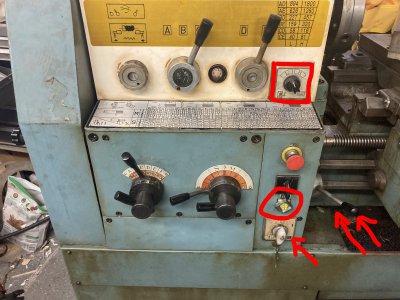
I wired up the VFD and tripped the white switch (red arrow) and the four little lights (red circle) lit up, but any time I would try to engage the lever (double red arrows), the VFD would throw an error code. I did here some noises coming from the wiring in the back, but I never heard the motor even try to do anything. I tried reversing the direction on the VFD in case I got it wired wrong, but it didn't help. I then bumped up the frequency to 120 hz, and it stopped throwing the error code, but I still could get the motor to engage. I put it back to 60 hz, and now the little lights won't even light up. I did try the coolant pump while the lights were lit, and it did activate. No wires were messed with except for the switch (red box above). It had to be disconnected to get the gearbox off when we were moving it. I labeled everything and put all the wires back where they went.
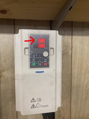
I've wired up 2 other VFD's, one for a mill and one for a surface grinder. There were the same brand, only smaller, and I had zero issues out of either. The only thing I noticed with the new VFD was the display for the Hz keeps flashing(red arrow below), and it didn't do that on either of the smaller ones. It also shows almost no draw being placed on it.

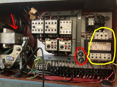
I did open the back panel and check what I could. The red arrow to the main switch is reading 120v into each wire. I did check the fuses(red circle), and they were all good. I also checked the voltages in the yellow circle, and none of them match up to what was marked on it.

I'm sorry if I sound like an idiot, but with electricity, I am. The picture of the back panel is literally what my nightmares look like. Can anyone give me some suggestions of things to try, or if not, who can I call to come and work on this type of thing?

I wired up the VFD and tripped the white switch (red arrow) and the four little lights (red circle) lit up, but any time I would try to engage the lever (double red arrows), the VFD would throw an error code. I did here some noises coming from the wiring in the back, but I never heard the motor even try to do anything. I tried reversing the direction on the VFD in case I got it wired wrong, but it didn't help. I then bumped up the frequency to 120 hz, and it stopped throwing the error code, but I still could get the motor to engage. I put it back to 60 hz, and now the little lights won't even light up. I did try the coolant pump while the lights were lit, and it did activate. No wires were messed with except for the switch (red box above). It had to be disconnected to get the gearbox off when we were moving it. I labeled everything and put all the wires back where they went.
I've wired up 2 other VFD's, one for a mill and one for a surface grinder. There were the same brand, only smaller, and I had zero issues out of either. The only thing I noticed with the new VFD was the display for the Hz keeps flashing(red arrow below), and it didn't do that on either of the smaller ones. It also shows almost no draw being placed on it.

I did open the back panel and check what I could. The red arrow to the main switch is reading 120v into each wire. I did check the fuses(red circle), and they were all good. I also checked the voltages in the yellow circle, and none of them match up to what was marked on it.

I'm sorry if I sound like an idiot, but with electricity, I am. The picture of the back panel is literally what my nightmares look like. Can anyone give me some suggestions of things to try, or if not, who can I call to come and work on this type of thing?

