Learning how to use the C Gorton 10” Rotary Table

Janderso

Jeff Anderson
H-M Platinum Supporter
Joined
Mar 26, 2018
Messages
8,413
I have been avoiding this,
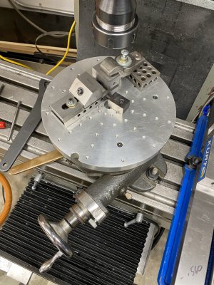
There are several good videos on YouTube that helped me get the basics down.
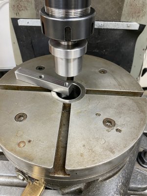
I think I just need to leave it on the table and play with it.
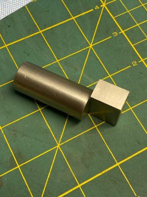
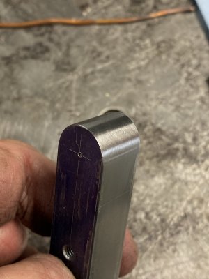
My parts came out ok.
 

Attachments

  • B3CCE21C-267D-48B2-B6BE-7841841BA6D5.jpeg
    B3CCE21C-267D-48B2-B6BE-7841841BA6D5.jpeg
    1.1 MB · Views: 69
  • 75DC77B4-F93A-4F87-A85A-78395FB1D992.jpeg
    75DC77B4-F93A-4F87-A85A-78395FB1D992.jpeg
    512.7 KB · Views: 59
Your Gorton looks a lot like my 12" Index brand rotary table. I say Index because it was built prior to Wells buying the company in 1971. I've been using mine lately to build a top plate for a lathe tool grinding fixture.

It looks like you've added a top plate for fixturing accessories. From the pictures the plate appears to be about an inch or so thick. Do you find it more useful than the standard T slots? Mine already weighs about 125 lbs. and it's a beast to move from the storage table to the mill. The addition looks interesting, but I really don't want to add another 20 lbs. to the table unless it makes it more functional.

Here's a picture of mine on the mill. The through holes were made with a different setup. Right now I'm adding the lines for the degree markings.
 

Attachments

  • IMG_1095.JPG
    IMG_1095.JPG
    91.8 KB · Views: 40
Your Gorton looks a lot like my 12" Index brand rotary table. I say Index because it was built prior to Wells buying the company in 1971. I've been using mine lately to build a top plate for a lathe tool grinding fixture.

It looks like you've added a top plate for fixturing accessories. From the pictures the plate appears to be about an inch or so thick. Do you find it more useful than the standard T slots? Mine already weighs about 125 lbs. and it's a beast to move from the storage table to the mill. The addition looks interesting, but I really don't want to add another 20 lbs. to the table unless it makes it more functional.

Here's a picture of mine on the mill. The through holes were made with a different setup. Right now I'm adding the lines for the degree markings.
The plate is just my way of adding fastening options.
I need to make some more hold downs and straps.
Lying awake last night, I am going through the set up procedures on how to position the work directly under the spindle so I can properly adjust my offset.
I over cranked so I need to pay attention to where I am in the process.
Some people make these things sing. Mine sounds like a kazoo.
I'm not sure how you position your table, but when I setup mine I first roughly center the rotary table on the mill table. Then crank the rotary table to 0* and align the hold down slots over the center slot in the mill table. Then I position a DTI against the edge of one of the T slots. I adjust the unit so the T slot is parallel to the table to within .0001" which is close enough for the work I'm doing.

Then I roughly center the hole in the table under the spindle, put a coaxial indicator in the spindle and adjust the X and Y axis of the mill table to center the rotary table. I generally start the spindle at a low rpm (less than 100) to make the needle move slow enough that it's easy to see when the rotary table is close to center. When I'm within a few thousandths I speed up the spindle to about 500 rpm and make the final adjustments. I then set the DRO to absolute 0 on both axis.

I now know rotary table slots are parallel to the mill table, and where the exact center of the rotary table is. I can now position parts relative to the X and Y axis of the rotary table, and have them aligned with the movements of both the rotary and mill tables.
 
For rough centring of the rotary table under the spindle, I will use an arbour with two features:
1) on the bottom end it has a Morse taper that fits the centre hole of the rotary table,
2) on the top end it has a cylinder that can fit into a spindle collet or chuck.
I put the arbour in both and then use the table X and Y manual feeds to move the mill table under the rotary table to line-up the t-slots for clamping.

For some jobs that is close enough.

For other jobs I move on to DTI or coax-indicator afterwards.

Many rotary tables have small key-ways and threaded holes in the bottom for use with small keys that get bolted on. These keys line up in a mill table t-slot to set the axis of the rotary table to that of the mill table. They can be a great time saver. You may need to make your own custom keys.

-brino
 
projectnut and brino,
Good advice, I like the idea of aligning the t-slot along the x axis.
I'm taking the advice of clamping to the table. The heck with the machinists vise.
I'm thinking this pin I bought from Joe Pie will help me align the vise or t slots of the RT.
I made a pilot/arbor that gets the RT very close, then I use the test indicator.
Warning, novice in training.
 

Attachments

  • pin.jpg
    pin.jpg
    59.3 KB · Views: 20
For rough centring of the rotary table under the spindle, I will use an arbour with two features:
1) on the bottom end it has a Morse taper that fits the centre hole of the rotary table,
2) on the top end it has a cylinder that can fit into a spindle collet or chuck.
I put the arbour in both and then use the table X and Y manual feeds to move the mill table under the rotary table to line-up the t-slots for clamping.

For some jobs that is close enough.

For other jobs I move on to DTI or coax-indicator afterwards.

Many rotary tables have small key-ways and threaded holes in the bottom for use with small keys that get bolted on. These keys line up in a mill table t-slot to set the axis of the rotary table to that of the mill table. They can be a great time saver. You may need to make your own custom keys.

-brino
Mine is a bit different in that the hole in the rotary isn't tapered. It has a bushing in it labeled 3/4". However it isn't actually .750" but rater .748". I made a plug to fit the hole, but just use it as confirmation that when I'm finished it's aligned properly. I insert the plug in a collet and lower the spindle into the hole in the rotary table. So far it's fit in smoothly every time. My table also came with keys on the bottom., but they were 11/16" which seems to be an odd size. I removed them thinking I would cut them to size as time allows. So far they've been sitting in the same spot on the shelf for over a year.
 
Last edited:
Mine has a straight pin as well.
I think there are advantages and disadvantages to both.
I’ll take some pics, I don’t know how to center the part.
The radius needs to be .312 (5/8 stock)
The cutter is 1/2”
Ok, .250 + .312 is .562. That’s the easy part.
How do I center the part to thy Y Axis?
The RT is zeroed dead center on the DRO.
Frustrating for sure.
 

Attachments

  • 9A1ABD10-47EF-4DC7-BEAB-362FAA05E90C.jpeg
    9A1ABD10-47EF-4DC7-BEAB-362FAA05E90C.jpeg
    1,010.6 KB · Views: 19
Back
Top