Lima Motor Rotation how to change

It looks like there are two leads going into the motor from each of the line connections.

One will be to the start windings, the other to the run windings.

Switch one set of the leads going into the motor. You can determine which of the leads going into the motor are a set by measuring with an ohm meter; the sets will have a low resistance, the non-sets will have a high resistance.

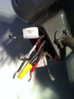
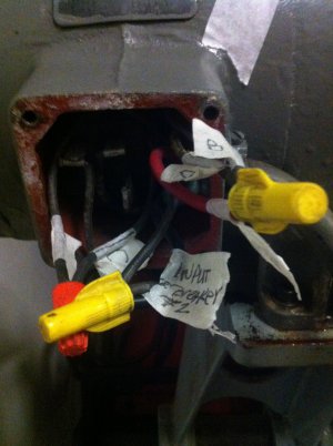
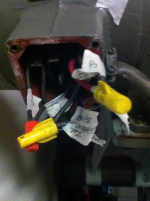
To try to make it clearer, the power comes in on the red and black wires.

There are two wires connected to the red wire (in the yellow wire nut). Label one A and the other B.

There are also two wires connected to the black wire (in the red wire nut). Label one C and the other D.

Use an ohm meter to measure the resistance between A and C, B and C, A and D, and B and D.

Two of the readings should be low; the other two should be high.

If A and C (and B and D) are low, move A to the black wire and C to the red wire.

If B and C (and A and D) are low, move B to the black wire and C to the red wire.

If none of the pairs are low, or if they're all low, (or if you don't really have two wires going to the motor from the red and black wires) then I have no idea what's going on with the motor.

Good luck!

Carl
 
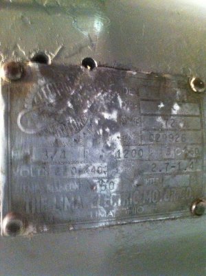
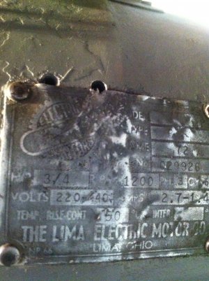
It was just a thought. The reason I was grasping at the straws so to speak is that the nmotor appears to be original and if it is, the I would venture to say thet it has been run in that orientation for a long while. That may even be the reason the Original owner got rid of it in the first place too. I am one of those who look for the most common and simplest fixes first before I start tinkering with the wiring. If you could post up all of the info on the date plate exactly as it is shown on the plate we could help determine exactly what motor you have and it's original configuration. Sorry about the wild goose chase idea, but like I said start simple and work up.

Bob
 
WOW!
It is a 3PH motor 3/4 hp runs at 1200 RPMs I had a friend of mine install the capacitor it basic give the motor a bump as if it was running on 3ph power.
A) Sure looks like a single phase motor to me. That black plastic gizmo in the peckerhead is an amperage sensing relay. This item opens the starting circuit when the motor has come up to speed. 3 phase motors do not need/use capacitors.

B) If I could read the nameplate we all would know so much more.
I can't photo the name plate as it is very worn and the little info on it is very difficult to read I have posted all the info I can read and thats with a magnifying glass
C) Seems it is a horizontal mill. My time on one is limited but what difference does it make which way the motor/cutter turns, If it is not right turn the cutter over so the teeth face the opposite direction. Is this silly thinking on my part?
It is a Horizontal Mill its a Burke #4 I finished my project the way you describe but that means I would be climb milling every thing and that is slow and hard on cutters and the table feed screw.
D) The motor is 1 phase or 3 phase, it can not be both. Neat set-up for speed control though. You've got like 12 speeds on that thing, right?
The motor is 3 ph running on single phase power thus the need for the capacitor to imitate 3 phase power. I believe its 16 speeds 4 different speed selection and 4 different pulley selections I could be wrong as I have never gotten to that level of use with the mill.

- - - Updated - - -

It was just a thought. The reason I was grasping at the straws so to speak is that the nmotor appears to be original and if it is, the I would venture to say thet it has been run in that orientation for a long while. That may even be the reason the Original owner got rid of it in the first place too. I am one of those who look for the most common and simplest fixes first before I start tinkering with the wiring. If you could post up all of the info on the date plate exactly as it is shown on the plate we could help determine exactly what motor you have and it's original configuration. Sorry about the wild goose chase idea, but like I said start simple and work up.

Bob
Bob,
Thanks for taking the time to reply. the name plate is so old and so worn I have to read the little data that I can make out with a magnifying glass,my eyes are getting old too.

- - - Updated - - -

It looks like there are two leads going into the motor from each of the line connections.

One will be to the start windings, the other to the run windings.

Switch one set of the leads going into the motor. You can determine which of the leads going into the motor are a set by measuring with an ohm meter; the sets will have a low resistance, the non-sets will have a high resistance.

To try to make it clearer, the power comes in on the red and black wires.

There are two wires connected to the red wire (in the yellow wire nut). Label one A and the other B.

There are also two wires connected to the black wire (in the red wire nut). Label one C and the other D.

Use an ohm meter to measure the resistance between A and C, B and C, A and D, and B and D.

Two of the readings should be low; the other two should be high.

If A and C (and B and D) are low, move A to the black wire and C to the red wire.

If B and C (and A and D) are low, move B to the black wire and C to the red wire.

If none of the pairs are low, or if they're all low, (or if you don't really have two wires going to the motor from the red and black wires) then I have no idea what's going on with the motor.

Good luck!

Carl


Carl,
I will give this a try today and get back to you with the results and thanks for the info and help Cory also suggested changing the wire from the capacitor I'll probably try both suggestions today
 
Gentleman,
All who posted help and hints it is appreciated. I spent all day working on the name plate for the motor I have attached a photo this is the best I can do with it.
Carl, I tried all the combinations with a VOM digital and Analog after marking the wires as suggested and the reading are as follows,
A to C = 3.19
B to C = 6.7
A to D = 2.537 and fluctuation and dropping
B to D = 6.7
I will switch the wires tomorrow and let you know what happens.
I worked on the name plate for 1 hour just too get what is in the photo, there is another plate which I suspect was the wiring schematic but it is no more its been painted over
but the photo shows the data from the manufacturer.
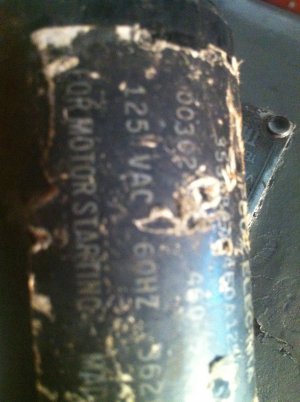
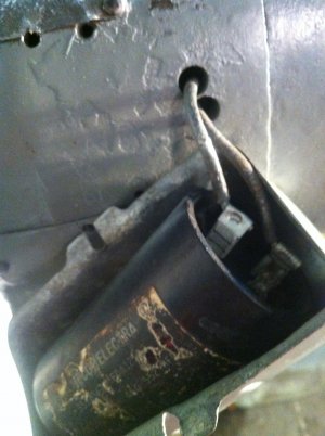
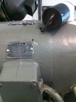
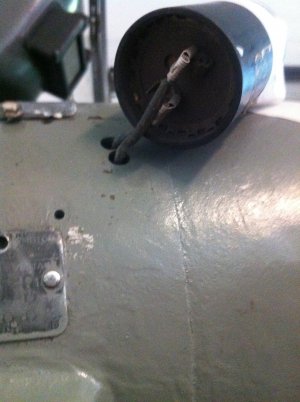
I also have close ups of the capacitor on the motor it seems to be a start capacitor so here are the photos

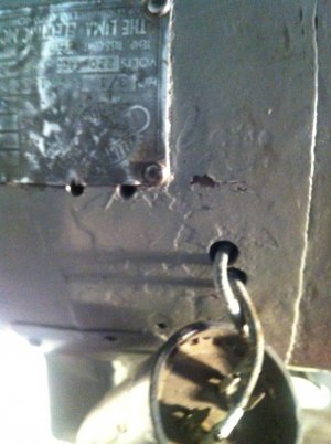
Lima motor tag.jpg Better photo of Lima tag.jpg Capacitor info.jpg Capacitor wires.jpg Capacitor.jpg Junction Box(Perckerhead).jpg
 
Amazingly enough if you use a little easy off oven cleaner on a shop rag you might be able to rub a coat of paint at a time off without damaging what lies beneath. We used to use it to clean our racks before repainting them to keep the chips to a minimum in the coat of paint. Just a shot that might help a little. The line with the dropping reading is the one with the cap on it more than likelu. Just be super carefull and don't get any in your eyes because it is essentially unslaked lye and will burn you badly.


Bob
 
Hey Bob ,
I'm being ultra careful with this thing as I do not want to smoke the motor as its basically irreplaceable,I'll give the oven cleaner a shot I have plenty of it from the dollar store.
It works well for cleaning but very slow at removal of paint. Again Thanks for the hint I'll post back in a day or two with the results and hopefully an image of the wiring.
 
OK, I am with Rbeckett on this one. Place I used to work had a saying "If it has a wire connected to it, it must be an electrical problem". Truth is it, is about 95% mechanical and 5% electrical for the fix. So lets back up and see if we can see the forest for all those trees out there.

The name plate says three phase. So we must have a source of 3 phase power and just a capacitor is not going to cut it. The HP and amperage draw is low enough that a VFD would handle the load. My mill has a BP vari-drive on it so I just use the VFD for the motor protection features, soft start-stop, etc. Mine is 2 HP.

Looking at the open peckerhead, if it is truly 3 phase what is the black relay box for? Thermal overload of some kind? If it is it should open at least two of the three legs to the motor. Lets pop the end bell off and see where the wires go and if there are things hiding in there we do not know about.

Thinking here, the name plate says dual voltage. Do we have enough wires to rewire it to 480v thinking it is connected correctly for 240v now? Could it be a wye/delta like the Europeans like to do? Does this tell us anything? I still have more questions then answers.

Does the table feed on that mill only work in one direction?

A three phase motor running on single phase only develops something like 28% of it's nominal HP rating assuming it starts at all.
 
The name plate says three phase. So we must have a source of 3 phase power and just a capacitor is not going to cut it. The HP and amperage draw is low enough that a VFD would handle the load. My mill has a BP vari-drive on it so I just use the VFD for the motor protection features, soft start-stop, etc. Mine is 2 HP.

Looking at the open peckerhead, if it is truly 3 phase what is the black relay box for? Thermal overload of some kind? If it is it should open at least two of the three legs to the motor. Lets pop the end bell off and see where the wires go and if there are things hiding in there we do not know about.

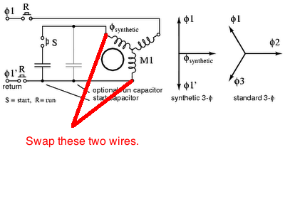
A three phase motor can actually be run off of single phase with just a capacitor. See this. This is how many DIY phase converters work, which is essentially what he has running on his machine. The capacitor delays the sine wave of one leg of single phase, just long enough to create a phase shift (as little as 5deg will work), which is enough to create a rotational energy in a three phase motor. There are many ways to hookup the capacitor, as described in the article. The motor is not as powerful running this way, about 60%, but it will run.

That little black box is still a mystery, but I am inclined to believe that it is a thermistor, rather than a relay.

I still have to go with my original assertion, that switching the wire coming from the capacitor, with one going to a winding, should change the direction of rotation. See the photo below. If this does not work, then there is something else going on in the wiring, and you should open up the motor some more and take a look.

Running 3-phase motors with 1-phase 01.png
Let us know what you find.

-Cody

Running 3-phase motors with 1-phase 01.png
 
Can you post a better photo of the mystery black box? I have a feeling that I might know what it is.

-Cody
 
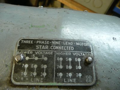
Here we go, these are the photos of the tag from the motor, the oven cleaner did work but the plate was very difficult to read, but a gentleman over on the burke yahoo group gave me a link to a photo of his plate as he has the same motor.which I have posted here.
The black devise in the peckerhead is marked " Micro Start" made in the USA. I have pulled all the wires and marked them the only thing that presents a problem is the number of wires,
The plate calls for 9 I have 8 and only 2 coming in from the service panel.
I'll check for continuity from the capacitor to the micro start device. I really appreciate all the expertise from every one as I'm sure you have surmised I know very little about electrical problems, but I do want to Thank all for the help thus far.


Star connected.jpg correct tag info for mill.jpg IMG_0169.jpg IMG_0168.jpg IMG_0166.jpg
 
Back
Top