Logan 9B spindle assembly

AR1911

Active User
Registered
Joined
Nov 5, 2010
Messages
871
Finishing up my rebuild of a Logan 9B28-1 lathe. Finally got a good spindle from Joe at Plaza Machinery. So today is Assembly Day.

I note that there is no provision for oiling the spindle pulley where it rotates on the spindle when in back gear. Most lathes have a "set screw" oil port in one of the pulley grooves. This has none. I looked at drilling and tapping for one, but it can only go in the smallest pulley groove, and it sure looks thin there. Anyone else here done anything that works? Mjenks?

Also I am pressing the nose bearing on, and it sure is taking a lot of force. Bearing and spindle are both clean, and I polished the spindle surface to ensure smooth assembly. Right now it's got about an inch to go, and I don't want to Load it up more than I have been to get this far. Of course at this point I don't want to press it back off as there is no good way to press against the inner race in that direction.
Seems to me it pressed off very easily.
Right now it's sitting in the freezer. Hoping it shrinks enough to get finished. Any suggestion welcome
 
Last edited:
I'm not familiar with your lathe, but another lubrication method I've used is to drill the shaft along its axis. If you can see one end of the shaft, then this could work for you. Drill about 1/3 the length of the shaft on a lathe, then cross-drill a smaller hole all the way through to let the oil or grease out mid-way between the bearings. Removing metal from the center of a shaft does not hurt the strength of the shaft either.

Consider that. :thumbzup:
 
This is not a solid shaft, it's the spindle. It's almost 1 inch ID.
 
OK, I figured out my problem. My press setup wasn't right, plus there were some burrs I had overlooked. So the bearing is now on the spindle.

Now I need to be sure I have the assembly sequence right.

From the right side, spindle nose:

Bearing

Right headstock casting

Bullgear and key

Main pulley W/integral gear

Collar with setscrew

Left headstock casting

bearing

2 Belleville washers, concave sides facing each other

thin spacer

Threaded collar

Is this correct?
 
Hey;

Another one not familiar with your model, but if it is built like a 200, everything regarding spindle drive Bull, cone, back gears, etc) goes on before the spindle goes in. Then the lead screw drive end stuff goes in from the left end after that. I would spend some time jiggering the spindle drive components around before putting the screw drive (left) end together. This will save time if you have to pull the spindle back out for some reason. I had mine out more than once for various reasons, and having to uninstall the screw drive stuff again would have been a lot of extra effort.

EDIT: I should say all that stuff is put in place AS the spindle goes in. You obviously feed the spindle THROUGH it as you install the spindle in the headstock.
 
Last edited:
Yessir, fully agree. I just need the sequence of pieces. Mine had been apart before I bought it and I have no confidence it was correct as I found it.

I probably should just by the parts breakdown from Logan, but I have been somewhat disappointed in the reprints from them of late. Seems you can buy better - print quality, binding - manuals but he is the only one with the parts diagrams.

At this point I am ready to assemble and don't really want to wait for shipping
 
I hear ya;

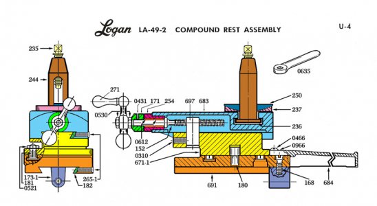
One of my favorite time wasters is to recreate the factory schematics so they look nice, instead of like a spilled bowl of popcorn on the page. I've gotten pretty good at it, even coloring some of them for clarity. Unfortunately for you they are for 200s. Not sure if they are all the same type parts, if not the identical ones, to your 9B.

Example;

LoganLA-49-2CompoundEarly.jpg
 
Hey;

Anyplace that a bearing sits, I always at least give it a rub down with a scuff pad, and many times light sand paper. Most times, there is enough corrosion or dirt or whatever present to defeat the light press/slip fit interface and cause problems with re installation. A light touch of grease on the surface also helps. This is strictly to remove FOREIGN material from the surfaces.

I do the schematic restorations either by drawing right on them in PhotoShop (JPEG/Pixel), or tracing over them and recreating them from scratch in CORELDraw (Vector).
 
Back
Top