[How do I?] MetalOxide Variator as braking resistor?

myxed

Registered
Registered
Joined
Jul 27, 2019
Messages
10
Hi All,
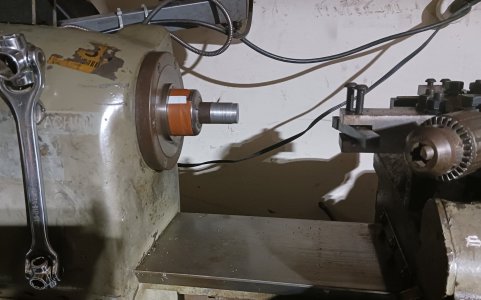
I have a Hitachi 2.2KW VFD WJ200-022 driving a Lathe -1.5HP, 1750 rpm 220v.The lathe is almost unusable because it errors out even without load with a one inch stock in chuck 5c collet.
I keep getting Error E05.3/ E05.4 I determined that I need a braking resistor.
From what I have read approx. minimum, 40 Ohm, 400W. I was looking at this 1000W, 100Ohm from Huangyang on amazon (B0791CLF8W)

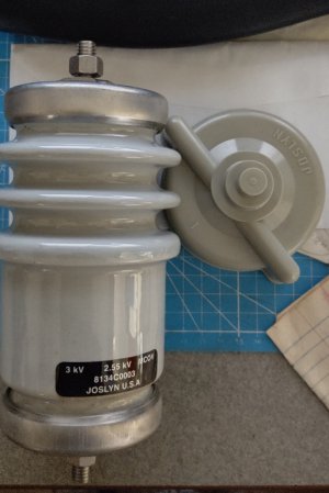
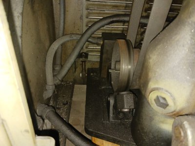
However, I already have this Metal Oxide Varistor . Can it be used as a braking resistor. Its been gathering dust for years(part of auction win years ago).
Cant find much data on this unit. Except it is 2.5kV MCOV . There is a stamp that says type 20 Metal Oxide.
No idea what Resistance is etc. Will it work? any particular cautions in installation?
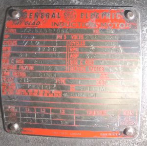
MOTOR Nameplate:
1.5HP , 1720RPM , 3 Ph , 3.1A, 208-220V, service factor 1.25

What I have tried.:
I tried V/F mode with motor data. Which improved it a bit , but not much.
I tried autotune SLV. which failed with motor run, but succeeded with motor static. Still Errors out with minor pressure.
I just downloaded the Hitachi software to try and set it up better.
but the usual stuff is already setup.
A044 =03 (from last autotune)
H003=1.1
H004 = 4 poles
Set motor amps B012 = 2.8A to leave some overhead (motor is 3.1A).
Set more parameters after reading posts here, but it gets confusing after a while.

Thanks for your help. Learnt a ton already from previous posts.
 

Attachments

  • VFDMOV.jpg
    VFDMOV.jpg
    263.9 KB · Views: 23
  • nameplate.jpg
    nameplate.jpg
    427.7 KB · Views: 19
You need to get a standard power resistor, you cannot use a MCOV. I would recommend a 50 Ohm 400-500W. Motor amps appear to be low for a 1.5 Hp motor, I would try 4.5A and run it in SLV. You might try setting H003 = 1.5. Autotune muse be done with the motor belts/drive decoupled.

This appears to be a 2 speed motor based on size and name plate, is it wired for the higher speed? If wired for the lower speed, than the parameters are wrong.
 
ThanK Mksj. That was quick.
I guess what I did wrong was autotune without removing belts (not looking forward to removing those belts). I tried in the past and it was a challenge.
I will try your settings and see if it improves. In the meantime I will see about ordering that braking resistor.
Electrical novice here. I wired that motor a while ago. I connected 3 legs from VFD to T11, T12 and T13 in the cabinet.
I have to move things around a bit to get to the back of the lathe to check the motor again Here is a pic from when I did it.. I dont know if this would help in diagnosing connections.
I measure 466 rpm @ 12hz and 620 rpm @ 20hz on VFD (non-contact tach. reading on chuck shown below) (my contact tachometer somehow reads 1125 rpm ...so I am not sure which to trust.) Leads me to think I am on the higher speed windings?

Will it be detrimental to VFD or motor if I got a bigger capacity (watts)...I think more ohms is not a problem right?
I am thinking for the price differential on Amazon between these resistors ....Braking-Resistor-1000w-Accessory-Inverter/dp/B0791CLF8W the various sizes maybe if there was any benefit such as less heat build up in resistor then the 1000w could work. It wouldn't let me post the whole link.
Or does it not work that way?

Thanks so much for your help to the community. Its many of your (and other members)other answers I read that brought me this far.
 

Attachments

  • motor wiring.jpg
    motor wiring.jpg
    341.6 KB · Views: 12
  • lathebelt2.jpg
    lathebelt2.jpg
    391.7 KB · Views: 11
  • belt1.jpg
    belt1.jpg
    217.4 KB · Views: 12
  • tach read location.jpg
    tach read location.jpg
    429.5 KB · Views: 12
Perhaps I could slack those belts and autotune and see if I can make it work. That belt tensioner all the way down might do the trick? Will try that.
Also, I noticed when I lower speed to approx 10 hz . I get a E05.4
 
Just do a static tune, you do not need to do dynamic make sure it is in SLV. Resistor size wattage there is a minimum but no maximum. The actual dissipation (heat) generated during braking is minimal, so bigger is not any better and you could probably get a 300 or 400W and be OK if not heavier loads. It seems like you have the motor running on the higher RPM, so base speed is 1720 RPM at 60 Hz.

You motor is drawing more current than the name plate implies, I would increase the motor rating to 1.5kW, the motor frame is very large for the Hp, I assume this is a Hardinge type lathe so the motor is a 4P/12P, as such the lower speeds were not meant to be run at 10 Hz on the motor. The usable speed range is more like 20-80 Hz, these motors are very well balanced but large for their rating due to the dual poles at constant Hp. It is challenging to setup the VFD to run both sets of poles. Is the VFD connected directly to the motor or are you running it through the switch gear and/or using the VFD as a power source for the lathe. The latter will not work.
 

Attachments

  • Hitachi VFD Troubleshooting and Error and Fault Codes.pdf
    928.6 KB · Views: 1
Yes , this is a Hardinge HC chucker. I will do a static tune to 1.5kw. and adjust the speed range.
I connected the power directly to the motor. I wanted to leave panel in original condition. So I disconnected T11-13 from the bus bar and wired them directly to the power from the vfd and grounded to the box itself. I am not using any of the hardinge levers or machine controls. It was a bit challenging to figure out how to wire stuff. I just made a little control box with Fwd, Rev, Start and a pot. Still a work in progress. I am starting and stopping from the VFD , but controlling speed from a Potentiometer in the control box (I can Start/Stop from my little control box, but momentary switches need to be changed to static ). I am ordering better switches to redo the control box so it can do all controls.
I power the 120V auto feed and DRO from a separate 120V extension.
Very much appreciate your taking out the time to help. Also, I will look into the attached pdf to further troubleshoot.
 

Attachments

  • WJ200 controls.png
    WJ200 controls.png
    23.6 KB · Views: 7
E05 is called "overload" by Hitachi but this term is not standardized and most other manufacturers use the word "overload" to mean something else. What Hitachi calls "overload," other manufacturers call "I²T Trip" or "Thermal Trip" or something similar. It is the result of an algorithm that tracks RPM and current over time to estimate how much heat has built up in the motor. For a given current, it will let you run longer (or indefinitely) at a higher speed because more speed = more cooling, if the fan is coupled to the shaft.

But the fan is not always coupled to the shaft. Sometimes the fan can be separately powered so that it is safe to run at higher current, at lower speed, for as long as you like. Other drives have options where you can tell the drive the fan is shaft-coupled or separately powered, and it will adjust its algorithm. Or you can simply disable it, which is often preferred if there is an actual temperature sensor in the motor which renders this algorithm redundant (and less accurate).

Since it has been said that your motor has a lot more thermal mass than a normal motor, it probably can withstand a good deal more time operating at low speed/high current than a normal motor. Considering that, and the fact that it has a 1.25 service factor, and the fact this isn't a motor on a conveyor 100yds from the nearest operator but rather something that will be running right under your nose, If it were mine, I would be comfortable with disabling this fault and just keeping an eye on the motor when running at low speed and make sure it doesn't overheat. But your drive does not seem to have any options for this. I only see b012 and b013. I would try setting b012 to 1000 and b013 to 01 and see if that makes an improvement. If not, set:
b013 = 02
b015 = 0
b016 = max
b017 = 50
b018 = max
b019 = 100
b020 = max

EDIT: I do not think a braking resistor is going to help with this fault. Braking resistor would help with overvoltage faults, which is a different issue.
 
Last edited:
We bought a CNC Mill nd a CNC Lathe (don't recall the make).
Both have breaking resistors.
What did they use you ask?
The used classic domestic stovetop coil burner units.
They are low resistance, high wattage and don't care if they get red hot.
Easy and cheap to salvage from an old kitchen stove.
If I didn't see these on new CNC equipment, I would not have believed it.
What?! LOL. That's something I would do on a home brew machine for my own use but not as an OEM. It's not a bad idea but it's kind of tacky. What manufacturer is this?
 
Thanks Guys,
I settings the ff. b values per Strantor's suggestion, and did a test run.
b013 = 02
b015 = 0
b016 = 11 Max
b017 = 50 ...This would not go beyond 50 before autotune. Now after static autotune Max is 100 , But I left it at 50.
b018 = 11 Max
b019 = 100 ...now 50 after auto tune.
b020 = 11 Max
TheVFD did not E05.x . It went down to 7.11hz, no error only for about 30 sec. with amps at 2.95
but VFD started getting warmer than usual about 35C. Lathe motor was at about ambient 32C. I was a bit scared to try for longer.
Even with tool pressure, no error.

Then I Auto tune with MKSJ's suggestion as ff.
B012=2.85A changed to 4A
H003 = changed from 1.1kw to 1.5kw motor power
H001= 02 Autotune selection
H002= 02 Autotune with motor stop
(Seems to be a discrepancy? in the manual pg 190 (of the 677 pg manual) #2 references an option of 01 for Hitachi STD motor but I only had options 00 and 02 ... did I misread that?) similar to MKSJ's spreadsheet.

Per the MKSJ spreadsheet,
Autotune settings:
A013 = 03 SLV
A044 = 01 Autotune with Motor Stop
B049=00 Constant Torque
B082 = 5.00 (range 0.5-9.99)
Values after autotune via VFD pane
F002= 5.0s from 14.87 before autotune
F003= 6.5s from 8.8 b/4 autotune ( I did try 2 sec and it came to a quick halt without error)
However , I will wait for a braking resistor before using that value)
H031= 163 Ohm
H032= 20.13 mH
H033=5.39A
H034=0.027 Kgm2

Thanks guys, the lathe is now usable. I will keep an eye on the motor temps, but in my tests so far there has been no significant change. However this was only a few minutes of testing.

I do have a 230v water heating element somewhere around here. Maybe I try it as a brake while I do my tests and before ordering the real brake? I do need to find it first to see what its specifications are,.

Should brakes be in an enclosure? I ask because of heat build up in an enclosure, yet I wonder if its safe to have a brake exposed, with all the volts dumped into it.
 
Back
Top