Method of attaching rods to rotor

It would be helpful to know what this assembly will be used for.
Airtight: At what pressure?
Most adhesive products can be released with heat. What temperatures will this be subject to?


Drilling and tapping for screws from the opposite side seems the most practical thing to do. Most thread locking compounds will also seal to some degree. Is there some functionality other than airtightness that precludes the use of countersunk screws?
Yeah, we try to help people with thus stuff and you have to fight to get all the design criteria one piece at a time. This is the second one in a week that we have gone through this.

I am done guessing.
 
I'm with Randy. Knowing the purpose of the design will go a long way to determining a course of action. Are there external forces at play that will influence the fastener design? Is there a mating part to this assembly? How air tight is air tight?

I would like to know how you intend to machine the the semi cylindrical cavities on a bench top mill to make them air tight.

Personally, I would go with @RandyM 's idea in post # 8. It is the most direct approach and least susceptible to machining inaccuracies. If an airtight seal is needed , it can be made at the surfaces between the rotor and the rods. Copper washers under the heads of socket head cap screws will also create a seal which will work with thousands of psi pressure or high vacuum. It's done with hydraulics and vacuum systems routinely.

As to tapered dowel pins, they are available with internal threads for the purpose of removal from blind hols.
 
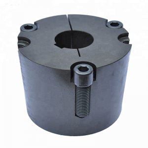
perhaps this locking concept might work.
taper lock.jpg
 
Is this turning in use? If so, how fast? Can you make a cap plate on both ends, drill and tap the rod ends and screw through the cap to get retention against the rotor and longitudinal control. Assuming rods are not hard. Do the rods control pressure behind them against the rotor? Your first idea is maybe fiddly. Need to put all the parts in the layout to check interferences. Sometimes magic becomes the only easy answer before something real shows up.
Yes it is turning. I dont know how fast yet, but maybe 5-6 K RPM. Yes the rods will have to seal against the rotor. It does not have to be a perfect seal, but as little leakage as possible.
I think this would be the easiest and if using set screws, the most secure way to make the rods removable. Setscrews are available with a 90°Cone-point. I would flatten the top of the stud so the contact with the hole is concentric with the tip of the screw, a slight countersink in the hole should suffice. The trickiest part would be offsetting the hole in the stud just slightly, so it is pulled towards the center of the rotor, when the screw is tightened.
Set screws against a flat in the studs are not going to draw it tightly in to the grove. And i am not sure what you mean by offsetting the hole in the stud to pull it in? Can you make a drawing of it?

I'm with Randy. Knowing the purpose of the design will go a long way to determining a course of action. Are there external forces at play that will influence the fastener design? Is there a mating part to this assembly? How air tight is air tight?

I can not show the total concept as it is a novel idea i think. But yes there is mating parts. It does not have to be totally air tight, but have as little leakage as possible with the design.

I would like to know how you intend to machine the the semi cylindrical cavities on a bench top mill to make them air tight.
Just with a boring head to be as close as possible to the rods diameter.

As to tapered dowel pins, they are available with internal threads for the purpose of removal from blind hols.

Hmm maybe roll pins and slightly offset holes in the studs to create a preloading. And the rollpins can be knocked out from both the top and bottom side if the hole goes all the way trough the rotor. But then we are back to really tight tolerances again.
 
Last edited:
I have a head full of ideas, but you failed to tell us the scope, application, forces, and conditions that this assembly will "see".

Recommend a bolt. <-- that may be a complete sentence, but it's an incomplete thought. See?

So I'm being helpful by suggesting you help yourself and avoid secrecy.

All four sentences in this post end with some form of "c".
 
Hmm maybe roll pins and slightly offset holes in the studs to create a preloading. And the rollpins can be knocked out from both the top and bottom side if the hole goes all the way trough the rotor. But then we are back to really tight tolerances again.
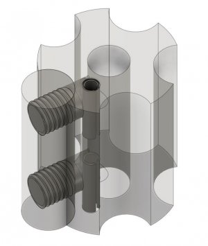
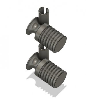
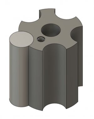
Or use groves in the side in stead of holes in the studs so the preload can be adjusted by how much the studs are srewed into the rods. Like this:
Rotor fastner2.JPG
Rotor fastner3.JPG
Rotor fastner4.JPG

Maybe the orientation of the slits in the rollpins will be critical for it to be able to flex to create a preload?
 
Last edited:
Protecting intellectual property can be challenging

Regarding your problem, is the overall shape sacred? If you can tolerate a .006" fillet on the inside corners, it would a candidate for wire edm machining. I have seen and held examples of wire edm machining where two separately made parts fit together so closely that you could not see the interface. If you are attempting to make a part for a prototype for proof of concept, it may be a viable way to go. Another approach may be 3D printing. Commercial enterprises are able to do some amazing things. One acquaintance is able to print working ball bearings. He can also print in stainless steel. Another is able to print in ceramics, again able to print working bearings. The accuracy and precision of these operations will certainly exceed those possible in a home workshop environment.


.
 
Back
Top