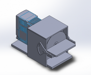
Mike's Slow Speed Carbide Grinder

Nice Idea! I left room to slide a pan under the disc to catch drippings, but not submerge the disc. I imagined a refillable tub on top with a needle valve to drip onto the disc. I like your idea though.
I stole the idea from the low-speed diamond saws we had at work, used for sectioning very hard materials. We did a lot of cross sections and polishing. With that setup, the (expensive) diamond saw blades lasted almost forever. We did have to remember to remove the blades once we were done, though -- the disks are made of steel and would quickly rust.

Talking about diamond saws, I also got a lapidary-grade saw blade I can install on my grinder setup. It makes it easy to nick a hunk of carbide or HSS to break it to a specific length. Something else to think about...and they're not very expensive, either. If you're sawing something by hand, don't twist the work piece -- the blade could catch and snatch the piece right out of your hand.
 
Designing the table motion to have a pivot axis at the wheel-table interface would be really nice. I'm imagining a four-bar linkage? I was playing around with this simulator.

I wanted the same action for my bench-grinder support, but no need for much precision, so I just used arc slots with a center at the support-wheel interface. It's a work in progress (slots here) but the prototype was good enough.

Yeah, That was a big deficiency I saw in the Youtube videos of these things. Mine isn't elegant, but by extending the walls past the face of the wheel, I could drill and tap the pivot hole in line with the wheel. The second hole will hold a bolt in a curved slot on the table arm for clamping.

Still working on the CAD for that.
 
Feel free to make it as complex as you want if that's your thing, but a perfectly adequate "MQL" system for this is that bottle of windex that you use to wash the windows. Give the disk a squirt when you start grinding and whenever it seems to be getting too dry. Done. Not sure who originally came up with windex - I heard about it from Richard King at his scraping class. Seems to work better than plain water.
 
I assume you've seen Stefan's version?
I wound up mostly copying that, using a small gearmotor that I found at HGR.
So far I've only used it for scraper blades, and my rest is literally a chunk of wood cut at an 8 degree angle with a miter saw and screwed to the base with drywall screws. Works great, but I plan to eventually add a tilting table.
Hey, you're 10 minutes down the road from me, we should do an HM meetup at HGR :p

I actually think I might get more use out of this for doing inserts, so I want the added capability to add cutting relief, hence the tilting table.

Looking to make this as easy as possible to build. Plates and screws pretty much. Maybe one CNC part for the pivot arms.

EDIT: I have seen his video. Like his setup a lot minus the big gap between the table and blade. Stealing his magnet and pin idea for sure.

EDIT #2: Don't have a welder so my construction will be different.
 
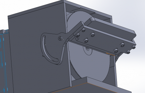
OK, Table is designed. It uses two 3/16" shoulder bolts as pivots and has a large swept arc at a 1.75" radius. A 1/4-20 screw on each side clamps the table in the tilted position. There is a sharp V in the middle of the arc which will act as a pointed to a graduated scale to be engraved in the side of the walls. I ended up with a +/- 45 degree angle for the table (not the easiest to achieve).

1613084657622.png

Here is the table from below. It uses socket head cap screws as fasteners. The table itself is blind tapped from the bottom and screws on the top of the support bar. Slotted clearance holes allow +/- 1/8" of travel on the table to set the gap between the edge and the platter.

1613084851099.png

I still need to model the graduated scale for the tilt angle, add fasteners to the walls, top, and base, add wire holes in the rear, add sheet metal around the drive and bottom of the platter, and add a provision for an angular contact ball bearing behind the platter.

Trying out Solidworks for the first time in 5 years. I usually use Inventor but they cut me off of student licenses. It is sorta like driving a car in a country that drives on the other side of the road. It all works the same but everything is in the wrong place.
 
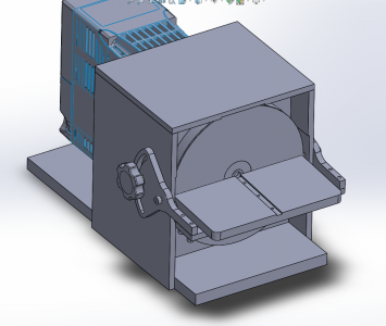
Updated shot with thumbwheel locking screws and a slot for a fence. Down the road I could make a set of fixed angle fences to sharpen carbide inserts to exact geometry.

1613086106119.png
 
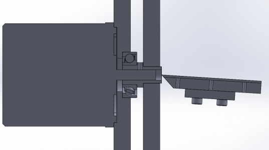
Had just enough room to sneak a 15x35x11mm 72xx series angular contact ball bearing into the design. This will add about $10 to the cost, but make it so that pushing on the platter does not cause the motor shaft to slide inward against the spring preload. I would have liked to fully enclose the OD of the bearing, but this will be fine (I don't have stock thicker than the 1/2" stuff I will be using).

This section view shows the motor (left), the front bulkhead with partially pressed in angular contact bearing, the shaft adapter with 8-32 setscrew bore just barely snuck in there, the platter, and finally the tilting work table with knife edge bevel.

1613087516906.png
 
Back
Top