Mini mill EXOSKELETON project for December.

Duke

Registered
Registered
Joined
Dec 30, 2018
Messages
73
So far I am extremely happy with my mini mill, but the following are a bit of a problem:
  • Column Rigidity
  • Vertical Travel (Especially since I have a large rotary table and grinding vise on it.)


Requirements:
  1. Increase rigidity
  2. Extend z travel by 80mm
  3. Z axis must be tweakable: side to side / forward back
  4. Must be undo-able in case it does not work.


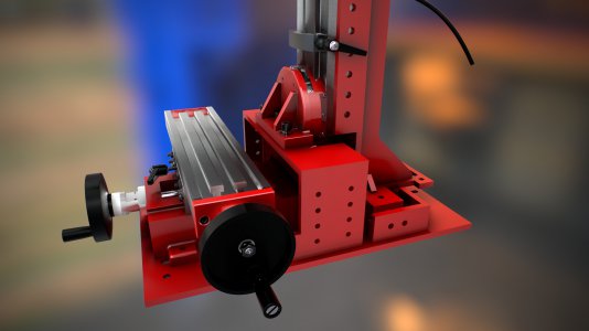
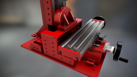
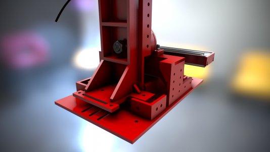
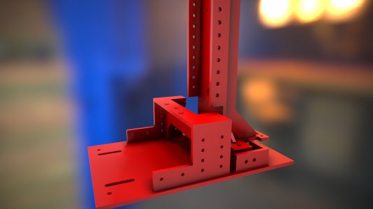
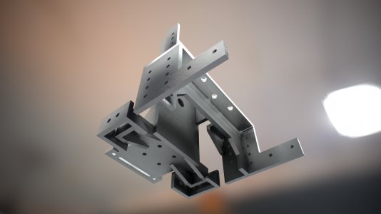
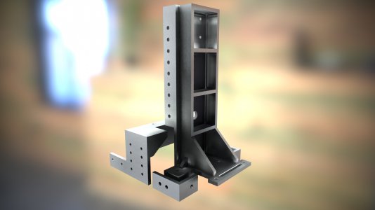
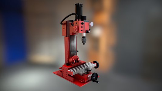
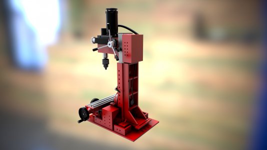
So this is the first prototype:

Designed to use 10mm steel.
Fully adjustable using 10mm bolts to tilt side to side and forward backwards.
The bridge lifts the column by 80 mm.
Slots for the base to shift forwards and backwards.

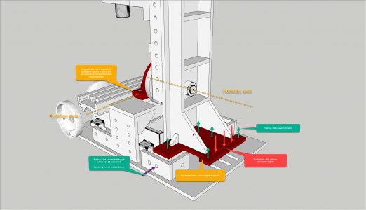
The bottom end of the column brace has all round clearance of about 15 to 20 mm. Using 10mm bolts it can be pushed/pulled in any direction. Additional bolt holes allow for the setup to be securely locked in place.

The base of the column is substantially increased : compared to the ridiculously small area under the three bolts that attach the column to the original base.

There are gaps between the vertical column supports and the mill's column. Initially I will use bolts here to hold the column in place / provide accessory mounting points.
screenshot000.jpgscreenshot001.jpgscreenshot002.jpgscreenshot003.jpgscreenshot004.jpgscreenshot005.jpgscreenshot006.jpgscreenshot007.jpg
 
there are non-tilting conversion columns kits available (plus 90mm z) and raising blocks 2",, your sliding feature looks interesting,, but it most likely will require tramming after every move..
 
It defiantly intrigues me. Will you be posting the models to Grab Cad? How do you intend to fabricate the frame? I imagine a lot of work in front of the bans saw or thermal cutter, or are you commissioning a cnc laser/watterjet/plasma cutter to make the flat pattern? For welding, how sophisticated of a fixture table to you have, or do you have access to a larger mill to make to flatten any inaccuracies from fabrication? or I guess you are making the matching assemblies float on one another then correct them with adjusting screws?
 
there are non-tilting conversion columns kits available (plus 90mm z) and raising blocks 2",, your sliding feature looks interesting,, but it most likely will require tramming after every move..

I should have used the term "tilt" to describe the movement of the Z axis. The whole idea behind this exoskeleton is for tramming the mill's column. ... and then holding it in place very securely.
 
It defiantly intrigues me. Will you be posting the models to Grab Cad? How do you intend to fabricate the frame? I imagine a lot of work in front of the bans saw or thermal cutter, or are you commissioning a cnc laser/watterjet/plasma cutter to make the flat pattern? For welding, how sophisticated of a fixture table to you have, or do you have access to a larger mill to make to flatten any inaccuracies from fabrication? or I guess you are making the matching assemblies float on one another then correct them with adjusting screws?

As far as possible I have designed the exoskeleton like an AK47 : lots of enineered slop and adjustability.

The most critical dimensions are :

  1. The three holes fixing the foot of the column to the bridge
  2. The distance between the slots in the base
  3. Also the top of the bridge has to be parallel to the baseplate

The frame will be laser cut by a local company - they quoted me about 80 USD for the steel and the laser cutting.

I will weld the frame myself. I have a number of square blocks and pieces to ensure that I get all the 90 degree stuff 90 degrees.

Welding will be cleaned using an angle grinder.

I will be using adjusting bolts at the end of the day to hold everything in place.

This is very much a prototype - I came up with the design in one evening.

In cross section, the back brace probably contains between two and three times the material of the original mill column.

design.png


100% correct on the adjusting screws:

The column brace floats above the table - about half an inch of clearance all round. The extra holes are for bolts to lock everything in place. The bolts simply push / pull against each other. Taking into account the force a 10mm bolt can exert I think this will be sufficient.
 
Last edited:
The extra holes in the side of the bridge are ffor attaching additional stuff. Better to have holes and not need them than needing holes and having to hand drill them.
 
The swiveling column mills are noted for lack of rigidity; the fixed column mills are better in that regard. Your cad drawings are well done- but I wonder if this inexpensive machine warrants all this extra modification? Why not just save your money and buy a bigger machine?
Mark
 
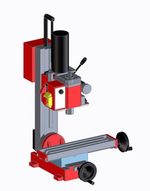
Nice job on the renderings. I know it’s pretty easy in the computer but still, I could look at stuff like that all day. :encourage:

-frank
 
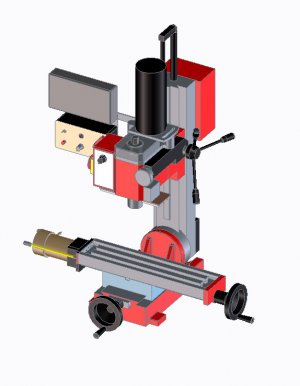
First off, that's an absolutely fantastic CAD rendering of your mini! Very nice detail. What software did you use? Here's the best I could do on my own CAD:
Left front top.jpgRight front top.jpg

Secondly, to gain additional Z travel (without extending the column), you might want to look into Little Machine Shop's air spring conversion kit. Along with the air spring replacement for the torsion spring and arm, it includes an extended rack. Yes, I know you're not within their normal shipping area. But maybe this will give you a worthwhile idea or two. You don't show any kind of counter-balance or spring in your CAD model, so I don't know what you currently have installed.

https://littlemachineshop.com/products/product_view.php?ProductID=2258&category=

Finally, you might want to consider filling the column with "epoxy concrete," both for vibration damping and for some added stiffness. There are lots of articles out on the interwebs on how to do this. But it's not rocket surgery. Just add clean gravel, sand, etc.to slow cure epoxy. I've done this to my mini-mill. Included a bunch of 1" long screws, to give "longer range" reinforcement to the epoxy mix.
 
The swiveling column mills are noted for lack of rigidity; the fixed column mills are better in that regard. Your cad drawings are well done- but I wonder if this inexpensive machine warrants all this extra modification? Why not just save your money and buy a bigger machine?
Mark

If I go for a new mill it will be something like the Optimum MH22 - over here they are available for about ZAR 34 000.

The upgrades on my mill will be about ZAR 800. - A lot cheaper.

Even though I can afford it, justifying that amount on a milling machine just for hobby use will be a bit difficult.
 
Back
Top