Mini mill vibrates a lot

Alberto, if your goal was to measure the flatness of your table, you now have some good information. If your goal is to tram the spindle to the table, ie make sure the spindle is square to the table, you are not there yet. I apologize for not clearly understanding what you are trying to achieve.
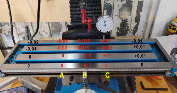
If you have been traversing the table across its X axis and Y axis travel limits, you have measured any variations in the table surface relative to the mechanical motion of your indicator. Assuming your setup is rigid, in the first picture with the red numbers, you have discovered that your table is higher on the left side (of the image) of the x axis, and is your table is higher to the rear of the table on the y axis. These numbers seem acceptable to me relative to the distances you are reading across.

To tram the table, you will need to measure differently.
 

Thanks for your answers.​

Shotgun

No no, For example, in the central mark, I fix the indicator. Dial to 0 and later I star movving thee table until I reach the upper way.

escalones1.jpg


So in "A" I dont move the indicator, I only move the table to get the 0, -0,02 and -0,04. Later I move the indicator to B and later C. Since the blacc numbers are so far, I need to move the table and the indicator, but once fixed, I don´t touch it until I get the 4 measurements.

Eyerelief

Yes, I´m triying to get the mill square. What I have to do? I was triying to doit ataching a square to he table.

mil.jpg

In A, I have checked the inclination of the colum along the X axis, in B the same but in Y axis and in C I have checked the inclination of the head, because in my mill is adjustable. In C i measured that the distance from the quill to the ends of the table are the same

Of course, for those measurements I attach the square properly, that setup is only to take the pictures to show you how I measure
 

Attachments

  • escalones1.jpg
    escalones1.jpg
    157.1 KB · Views: 117
Last edited:
okay, wait....... do you really mean +1mm here?
1651077163897.png


1mm ~= 0.040" ......that would be a huge lump in the table!

If this is real, then you should be able to place your square there and actually feel it rock over the high spot.

Hopefully that's a typo and it's actually "+0.01 mm"

Brian
 
okay, wait....... do you really mean +1mm here?
View attachment 405300

1mm ~= 0.040" ......that would be a huge lump in the table!

If this is real, then you should be able to place your square there and actually feel it rock over the high spot.

Hopefully that's a typo and it's actually "+0.01 mm"

Brian
Ooops no no, i forgot about tte 0,0 sorry. Is 0,01

I have edited the post. Thank you for warn me

by the way, I use metric because I see tin the forum there are some nationalities. But if the language of the forum is imperial I´ll star to speak in imperial.
 
Alberto, There are many options and tools for this procedure. The description is more difficult than the process.

Fundamentally, you need an indicator that can be attached off center to the spindle. As you turn the spindle around, you wilI take readings from the indicator (s). In theory when the spindle is square to the table, no matter where the indicator sits on the table, the readings will be the same when table variances are considered.

One of the most straight forward tools is a spindle square or tramming tool. Here is a picture.
1651075435869.png

Here is a basic set up video. Notice the use of the magnet? This insures that you are setting both indicators to zero from the exact same place.

A spindle square is not required, many people use an indicol or some other device which allows the indicator (s) to be offset from the spindle. Being rigid and square to the spindle when mounting your indicator is required. It would be difficult to achieve this with the bar stock mounted indicator you showed in one of your previous photos, but you were on the right track.
 
Thank you. Ok ok, but since I have spent a lot in tools I´ll try with the square but avoidiing to attach the base of the indicator to the bar.

And one last question. How much tolerance are aceptable for a hobby machinist? Because you know, the finest settings will be the most dificult
 
Yes, of course is your point of view, but for me is a valuable starting point, Thank you very much for the data!

To be sure
tol.jpg


If A = 5" B could be up 0,005 thou, right?
 
I apologize, I am being confusing. When I say "square to the spindle", I am not implying that you should use your square against your spindle. I don't think that gives you enough information to make an adjustment. I am trying to describe an indicator positioned approximately 63mm from spindle center that is at a perfect 90 degrees to the spindle. When the spindle is rotated 180 degrees, the indicator will be 126mm (5 inches) from its original position. Here is a picture of a shop made spindle square (not one I made) which if properly built would get you close. The round bar needs to be at 90 degrees when fastened to the flat bar, and the indicator should also be at 90 degrees when fastened to the flat bar.
1651079718266.png
Fearing deflection or flex, I would not have that much round bar sticking out of a collet if I was to make one unless the round bar was greater than .500 (12.7mm) or greater in diameter.
 
Back
Top