Theory...
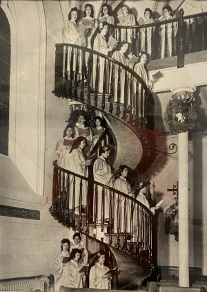
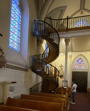
I also visited the church many years ago. As a hobby wood worker and knowing that the artist/wood worker only had hand tools at that time it is indeed impressive. However, when I was there I could not get up close and touch it or examine it closely. Just think this is located in a desert like climate. The carpenter had to even go to the mountains and haul in the trees to make lumber etc. What a task. Today people would be putting steel into it! I did not get close enough at the time to see if there were any nails in it. Screws would have been very unlikely. Anybody know? Did he use pegs? Did he have to go to a black smith to get nails made? If I recall correctly, part of the miracle was that the church had been built, but the sisters did not have way to get to the choir loft area, knew of no one who could solve their problem, and did not feel that they had room for a conventional set of stairs. This unknown stranger, carpenter, just showed up, built the staircase and then moved on!
For sometime, I also pondered on how it got its strength to hold up all of the people at one time. I doubt that there was a formal engineering theory at the time but things like this had been built long before.....of course today with modern modelling tools one could design one before building it. Before modelling however there is a mechanical theory of concerning the number of members and constraints needed to prevent motion.
For an object with a given number of sides there has to be a certain number of connection points for it to be rigid. If you look up "truss" on the web you will see lots. For example, queens truss roof, or kings truss roof, are commonly use to describe roofing. A kings truss in its simplest form has three sides to form a triangle. While it might fall over sideways the corners cannot move. It is similar to a teepee in that it is cone shaped to prevent the individual triangles from falling sideways. Anyway, the triangle has three member sides, and has three joints holding them together (two boards at angles and the ground is the third side. the connection points are at the top and the two where the boards connect to the ground and cannot side outward. (the teepee uses the cloth/hide covering to partially hold the bottoms in place. In a house, the ceiling joist form the bottom of the triangle as these joist are nailed to the two angled sides while the peak is nailed together. In the queens truss there are more members and so need more connection points. The simplest one is to take the triangle shape and cut the top off. Then put in a horizontal member across the cut and attach the ends. So it has 4 members, including the ceiling joists to form a trapezoid. So there are 4 members and 4 connection points. However, this is not stable as the whole thing can tilt as it would rotate on the corners. Hence, for the odd equal number of members and connection points of the kings truss it is stable, but for the even number of members and connection points of the queens truss it is not is not stable. However, the formula is not just odd and even. Think of this like a cardboard box that has it ends open. If you push sideways on it it collapses but if it were triangular in cross-section it would be rigid. So to make the queens truss viable another member and connection point is needed. It is commonly referred to as a post. From one of the roof corners run another member to a second corner so that the post causes two corners to have three member ends and it will now be stable. This structure has 5 members but only 4 connection points. We have effectively combined to triangles. In a house, the additional member commonly runs from the floor to one of the roof corners, and so it called a wall! Also since a wall commonly runs vertical and ends at the floor and not at the floor joist it is only a compressible constraint and does not prevent the roof corner from lifting up, hence two walls are used. One at each of the upper corners to the floor.
So think of the stairs. What if one just took a long board such as the hand rail and bent it into this spring shape of the stairs and fastened it at the floor and the top. It would be stationary at the ends, but would tend to flex/compress if weight were put at any point along the curved path. Think slinky toy, a spiral. It would also tend to bend sideways if pushed on sideways, but not as easily. Now put up another long board such as one of the edges of support for the stair treads. It would bend and flex in the same manner, but if you tie the two together with the balusters then the ability to slink decreases significantly. The top rail and the bottom rail is sort of like a ladder with the rungs being the balusters.... and it would still slink some if the balusters are only tied at two points. But in addition to the Balusters being attached at the top hand rail they are are also tied both at the top of one stair tread and at the bottom of the next one down and the tread support provides yet another triangle. Now the side cannot slink! The sideways motion is secured in a similar manner via the treads, the tread supports and stiffness of the balusters. Clearly there are lots of members and points in the stairs and they all work together, but I really think you could hardly build one without the balusters. The spiraling slinky is made stiff by connecting one loop of the spiral to the next and to the next along the outside. Three spirals connected at three points again and again. The balusters form the interconnections of the three spirals. With these interconnections you no longer really need the connection points at the ceiling and the floor. It will just stand up on the floor. However, I am sure that this stair case was fastened a little on each end to prevent wobble.
PS. My house was built in 1930 and has a queens truss design. I figured this out because I wanted to remove some walls, but was concerned because the entire roof, except for the 14 degree sloped top part, where the triangle point is missing, is covered in thick slate. Of course this old house also has thousands of nails holding the many connection points together. The only thing the walls do is to keep the house from collapsing when a strong wind would blow against the side of the queens trust shape!
Dave