My adventures with my RF-30

In this thread I will document my adventures in getting this mill from the dealer to up and running in my garage. I have another thread here that documents some of the early research and mills I looked at.

I just bought an RF-30 clone. It was originally sold by Rutland Tool, which I remember as a local SoCal company in the 80's. I bought it at a machinery dealer in Pomona, Wheeler Machinery. Nice people, very reasonable to deal with. I was pleasantly surprised. I got the mill and a 5" Kurt vise for $975 out the door. After the sale I asked if I could get a t-shirt, too, and they said yes.

1. LOADING
They loaded it with a forklift into my truck. I have a Chevy 1500 so the 600lb weight was no problem. The put a 2x4 between the quill and the column and picked it up with a forklift. It balanced really well and the 2x4 held the weight just fine.
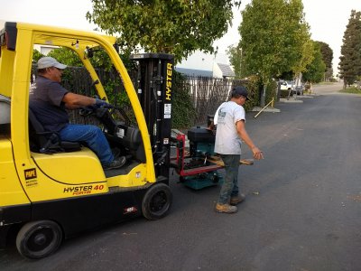
IMG_20201026_165216372.jpg

Once in the truck they pushed it to the back with the forks.
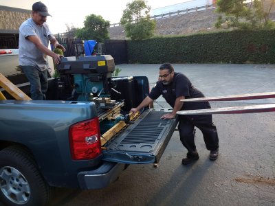
IMG_20201026_165515507.jpg

I tied it down with just two straps wrapped around the column. It didn't move at all.
 
17. BOLTING THE MILL STAND TO THE FLOOR
This was pretty easy. I located the mill where I wanted it, then drilled thru the holes in the mounting brackets that are welded to the mill using a hammer drill. I then tapped the anchors in and secured them. Make sure to put the nut at the top of the bolt and tap gently. It should go in fairly easily. I did one hole, bolted it, then another and so on. I had to put a sheet metal shim under one since the mill rocked a bit.

18. VISE
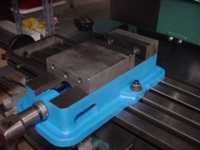
I got a Kurt vise included when I bought the mill. It's an A50/D50. I've documented the disassembly and cleaning here for those of you who are interested. I bought new mounting studs and bolts, since the other ones didn't match and that bugged me. One of them was also starting to crack. Got them at McMaster-Carr. Ordered them Friday evening and they arrived Saturday!

DSC00348.JPG

Next: tramming the mill and getting the vise square, then taking a test cut or two.
 
Last edited:
19. TRAMMING AND VISE ALIGNMENT
The tramming and vise alignment went surprisingly well. Only one corner of the table was off by 0.0015" and that was over 27". I was able to get the vise aligned to within 0.0015" as well. It moved a bit whenever I tightened the bolts. Drove me nuts.

I used a DTI that reads to the nearest 0.0005". I placed it on a rod extending at right angles in the mill, locked the quill and moved the table to the far left and right, back and front and watched the indicator.

I was expecting it to be off more based on my LMS 3990 being off quite a bit. I had to add spacers under the column on that mill. I wonder if I missed anything?
 
When I aligned my vise I discovered that the fixed jaw past the screws was off by .001 on each end. The jaw between the screws tracked spot on. Talk about frustrating until I figured this out. When aligning the vise tighten one bolt fairly tight such that you have to tap the vise with a hammer to move it. The other bolt only needs to be snug, not tight. You want to be able to move the vise. As you move the DTI across the fixed jaw keep lightly tapping the vise to bring the DTI to zero. Should only take one pass to align the vise.

When I trammed my mill I marked four spots on the table one for each of the four bolts in the same pattern if that makes sense. I put the DTI in the quill and measured each spot. Zeroed the DTI at the highest spot. Then measured the other 3 spots. This gave me how much I need to shim each of the lower spots to equal the highest spot.

Another interesting way I read about tramming a mill was to put a piece of soft copper wire around each bolt and spread thickened epoxy between the column and the base. Then carefully tighten each bolt until you got equal readings on the table. The epoxy will ooze out of the joint. Let the epoxy cure for a couple of days. Kind of similar to bedding a rifle action into a stock. If you don't want to glue the column to the base you should put mold release wax on the surface of the column and or the base.

You should be able to get both the vise and the column trammed to less that .001. Being off by .0015 is too much.
 
19. TRAMMING & VISE ALIGNMENT, REVISITED
I re-did this. I put the belt on the pulley to keep the DTI from rotating as it was dragged across the vise. I also made sure to tighten the head, vise and spindle bolts and locks.

The vise is now dead on; the DTI hardly moves at all, so it's within 0.0005" or less.

The table is within 0.0005" at the 4 corners. I made sure not to move or touch the DTI when I was taking the measurements. I did have to rotate it when I moved from one one of the table to the other. I rotated it using the pulley so as not to disturb the arm holding the DTI. I also rotated it and took measurements at various points on the table and the DTI didn't move more than 0.0005". I repeated this several times and got the same results.

A. Is this typical?: I noticed that if I tightened the top head bolt, the head "nodded" about 0.0005", then when I tightened the bottom head bolt, it nodded back the same amount.

B. I'm wondering if I should do it again a different way to see if the results are the same?
 
Way to go Jeff. Not unusual for the head to move slightly when the bolts are tightened. My head has three bolts. I had read somewhere shortly after I got my mill to tighten the center bolt first before tightening the top and bottom bolts. Try setting the head height based on the Lazy Machinist's longest tool methodology. Since I did that I have not had to move the head on my mill. ER collets have the most wiggle room to help with changing tooling. A drill chuck has the least when you get to larger size drills and you can't use it for milling anyway. Easier to stick with the ER collets.
 
If the head is back to zero when the bottom bolt is tightened, I say no harm, no foul.
Kinda like life, a series of trade-offs.
 
I'm making some parts for the DRO for this mill with this mill. The dials have some slop in them, but once I take that out, they are giving me the correct dimensions to within 0.001" or so. The z-axis dial has a really wide indicator notch so it's hard to get it exact every time. The y-axis handle was moving when I was making cuts, so I had to tighten the gib screw. Everything else worked really nice. I was taking 0.040" cuts in aluminum with a 5/8 diameter cutter. That leads me to this question:

MAXIMUM CUT
20. What is the maximum cut this machine can make?
My LMS3990 would take 0.025" cuts in steel with a small diameter (1/4") bit. I realize the answer will depend on the cutter, lube, speed, etc, but is there some guidance for this machine?

DUST COVER
21. Does this need any grease?
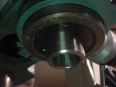
It had a glob of it. I had this cover/anti-dust plate/spindle cover (not sure of the name, the parts diagrams I have list several different names), come loose and get grease all over me. I didn't even know this was a part that needed to be taken off and cleaned; I missed it when I was cleaning the machine. The spindle rotates the same direction as this part unscrews, so I had to tighten it down just more than finger tight to get it to stay.

This is a view looking up at the spindle.
DSC00402.JPG
 
22. DO I NEED A OILING ACCESS HOLE HERE?
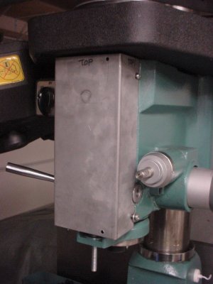
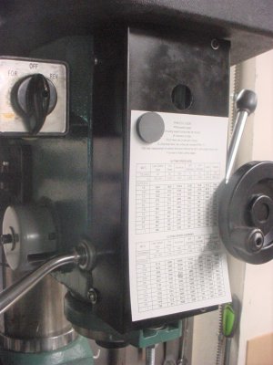
I've made a cover for the front to replace the old one, which is broken (I'm attaching a DRO, but that's another story). Does it need an oiling hole so I can oil the quill? I can oil the quill when it's down, but like the idea of oiling it at the top so the oil drips down. I've circled the area for the hole in pencil on the sheet metal. Thoughts?

DSC00403 (2).JPG
 
22. I regularly oil mine from the top. I take the cover off to do that on mine. But yours is different from mine. Make the hole big enough so that you can oil both the outside of the quill and also the inside shaft that spins.
 
22. DRO's

X-axis

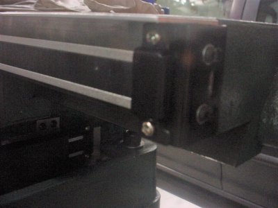
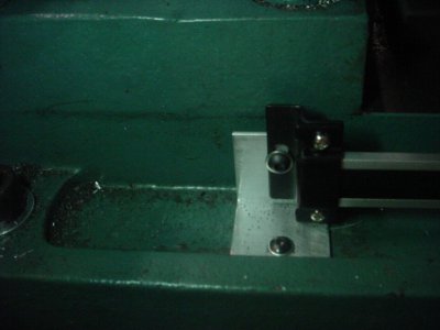
Here's a close-up of how I attached the rail to the table. I just milled a block and bolted it to the table and bolted the brackets to the block. The thru-holes are a little oversize to allow for adjustment.

I don't have a decent image of the bracket that holds the reader to the table. It's a piece of sheet metal I bent and cut slots into. The slots allow for some adjustment. I mounted the reader and the rail, then used transfer punches to locate the holes for the sheet metal bracket. The holes are slightly oversize to allow for adjustment.
DSC00475 (2).JPG

I use a piece of aluminum "L" as a cover.
DSC00476.JPG

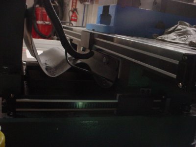
Y-Axis
Here is the overall design.
DSC00472 (2).JPG

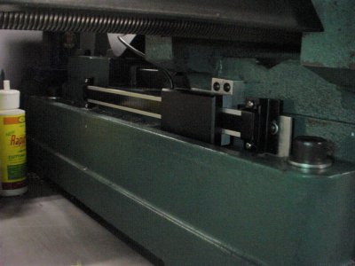
Close-up of how it's attached. This is at the rear, but the front is the same. The slots in the rail brackets allow for adjustment as do slightly oversized holes in the mounting brackets (shiny aluminum pcs).
DSC00473.JPG

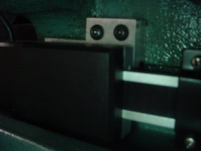
Close up of how it's attached to the table. I made the reader holder out of aluminum, assembled the holder to the reader and then located the mounting holes by using transfer punches. The holes were only slightly oversized for adjustment purposes, since the slots on the brackets allowed for adjustment.
DSC00474.JPG

Z-axis
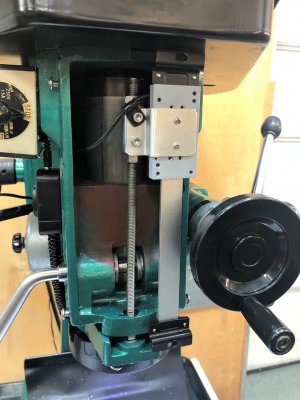
I used an idea I found on this site. This is the way it was done:
z-axis DRO install 0.jpg

Here is mine:
DSC00477 (2).JPG
I attached mine with nuts and bolts to the cover I made. You can see them in the upper right and lower right (barely). I made a speed chart and used a magnet to attach it. The hole if for lubing the shaft. It came in handy for making sure the wire cleared the spindle.
 
Back
Top