My little 7x14 is now ready to be cleaned, fettled and the rest

None of my plastic change gears are showing any signs of wearing out. They are so old that the lathe has a 3 digit serial number (184). I'm the 3rd owner, my buddy got it in 98 from the guy that bought it new.
That's reassuring to know. Hopefully that'll mean I can save the money for something more useful. :)
 
In my opinion bearings should never be installed by hammering-
A press or some type of threaded puller/pusher should always be used instead
Personally I would use the bearings it came with for now, you might get quite a lot of usage from them

I bought a hydraulic puller from Harbor Freight....

At least the forum is more civil than the spectating the Houses of Parliament!

Here's one, but I didn't check the .co.uk site. It installs and removes. Check to see if these tools come with the sizes you need first.


Preload is a big deal, because things warm up in operation, and the tighter they are, the more it adds to heat. The bearing manufacturer may specify a preload torque. In those cases, you can a "fish scale" or hanging spring scale (not digital) to pull from a known radius to set preload. You can also do it with a temperature gun in some cases.. Bearing manufacturers provide info too. And then there's always the wheel bearing technique... There are people here who definitely know more than I do about bearings, so I suggest posting a query thread and seeing what rolls in (pun intended).
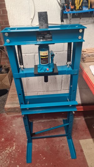
Just a quick update (and of course a big thank you ;) ) to those who commented on spindle and bearings removal: I bought a bearing removal/installation kit and tried a few configurations but in the end, I just got too antsy about potential damage both to the surfaces I was putting pressure on via the screw action and the internal bore of the spindle. So I ended up getting one of these from Amazon for about £130:

IMG-20231020-WA0004.jpeg

Everything became a lot easier after this arrived, I can tell you! :D I did use some of the plates from the bearing removal kit, so that money wasn't wasted.

Tonight, reassembly and relubrication begins. Should have most of that done by end of Tuesday evening (being a hobbyist I am forced to work during the day; I always knew I was born into the wrong class! :D) apart from setting the preload on the bearings. That might take another full evening.

Then all remains is doing the headstock and tailstock alignments and levelling the bed. I've printed out "Rollies' dad", have some drill rod going up to half an inch dia. and plenty of shim (I know it makes sense economically to these companies for this to be the case, but I really was amazed at the consistency of the thickness of the cans of Pepsi and Coke that I've cut up; oh, and handy tip: do not tell people you need pop cans for shim material: I now have a lifetime supply of shim material and a number of yet to be cut up coke cans that would cause a local authority's recycling facilities to close their doors for a week or two to catch up! :D).

Oh and props to the Grizzly manual writing folks. The nearest equivalent Grizzly model to mine (it's close enough) has a manual that is an exemplar of great text/image layout and good technical documenation writing at an appropriate level for the product. That, together with the ArcEuroTrade 'picture story book' style documents about disassembly/reassembly and bearing replacing have made this whole process a lot easier and less terrifying than it would have been otherwise.

Thanks to those and the great people on this forum, I might even get to make my first machinists hammer (always had a thing about hammers, even as a young child) before Christmas comes at this rate. :)

And I know, I know, pics or it didn't happen. Well, I promise you, nothing is going to stop me from boring the pants off every one (including, I'm afraid, you chaps) when I have an acceptably presentable tool that I made. :D

Cheers all.
 
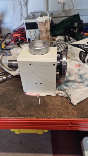
Well, it all got a bit delayed but I've finally got the headstock back together.

IMG-20231109-WA0007.jpeg

The bit of aluminium on top is a bit of scrap that I cut the center out of with an annular cutter on my drill press to use to press the rear bearing in.

The more observant amongst us may have noticed that the colour of the headstock paint has changed. If anybody is interested (hell, even if you're not; I like to ramble!) I'll post more tomorrow, including about my mishap with the hydraulic press... :D
 
As a programmer, I should have learned by now not to provide delivery dates but estimates. "Tomorrow" is now two days later :D

So, as I said, the headstock is a different colour. That's because it's a new headstock. That cheapy Amazon 12T Hydraulic press that, let's face it, we all doubt the 12T spec? Well, whatever force it is capable of putting out, it's quite a lot.

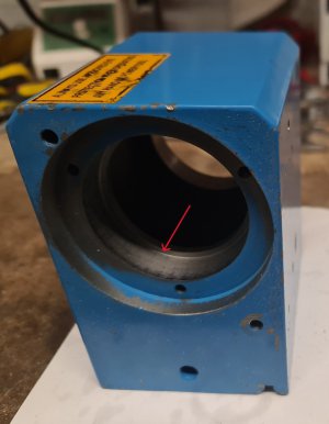
Here's a picture of the rear bearing location on the old headstock:

20231111_163704.jpg
The red arrow points to the bearing 'registration surface'

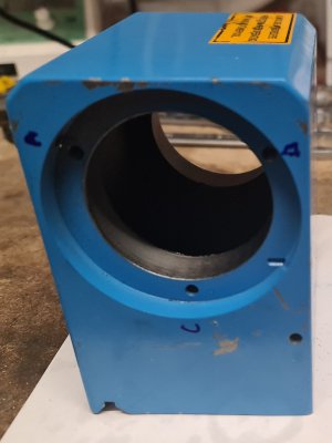
Now here's a picture of the front bearing location:

front_bearing_location.jpg

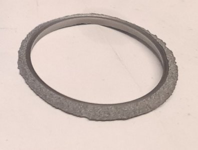
There's something definitely missing here; it's this:

ring_of_shame.jpg

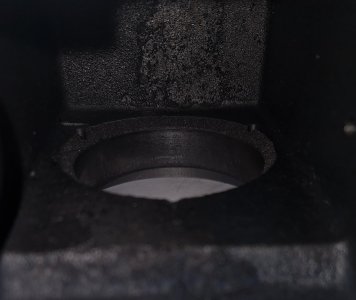
Here's the front location looking from the inside:
20231111_164029.jpg

Yeah, that's a bit of a mess. Turns out if you press too hard, that 'lip', the 'registration surface', can shear right off!

So I went to order a new headstock casting and it turns out that a whole headstock assembly (complete with the gears and spindle) for the older hi-low geared version of my lathe was only a little more expensive than getting just the new headstock casting specifically for my lathe and more importantly the latter would have required a wate of a couple of months; both are dimensionally the same and have the same fixing holes so I ordered the assembly.

I did consider leaving the hi-low gears in, but I'd have required a shorter v-belt than the one I have, or I'd have had to move the motor a bit further away and I figured at this point it was better to just remove the gearing and cover the holes for the hi-low gear lever and the ancillary shaft to prevent chips getting into the headstock, get the lathe reassembled and lubricated and start making some chips.

I do have to set the preload for the angular contact bearings first though. I already have a dual channel digital thermometer that takes a couple of thermocouple probes (bought to test the correctness of the PID controller I installed on my Gaggia Classic espresso machine) which I can use to check temperatures on the bearings don't rise too much, by taping the probes to the headstock casing at the appropriate positions.

Anyway, lesson learned: be more cautious when using the hydraulic press! :D
 
Ah, there is one more confession to salve my 'newbie machinist's soul'.

Having used too much force to press the spindle into the installed bearing and thus shearing off that 'lip', I'd also managed to get the inner race of the bearing well and truly stuck on to the spindle. When I got the spindle out of the damaged casting, the outer race of the stuck bearing had come off and left just the inner race behind. I could not get my thinnest feeler gauge (0.04mm) between the front of the inner race and the rear of the spindle head.

I did have the new spindle from the new headstock assembly but the keyway at the rear of the spindle shaft didn't match the length of key to hold the drive spindle pulley and the gear that engages with the change gear mechanism. I wasn't confident of my abilities to lengthen the keyway with my equipment (a drill press, a Dremel and a set of files!) such that it would be accurate and not lead to some slop. By the way, I didn't take any photographs of the stuck spindle in-situ as I was pretty depressed at this point (it would have been that two month wait for a new spindle, just like the headstock casting). So anyway, it was a case of trying to rescue the existing spindle.

I tried leaving the spindle in the freezer overnight and then heating the stuck inner race with a propane torch to loosen it but all to no avail.

Then, I tried to chain drill a line of holes in the inner race (front to back) to release it from the spindle. Well, you'll guess how that went, given how hard bearing races are. Even at it's lowest speed (the one I generally use on steel) I couldn't get a decent mark with my centre drills in my drill press.

In the end I decided to grind the inner race to split it just enough and get it to loosen.

This I managed to do:
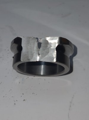
20231112_114516.jpg

However, I was a little clumsy with my grinding and I did end up taking off some material off the rear of the spindle head as you can see here (this is with the new bearing fitted to the spindle):
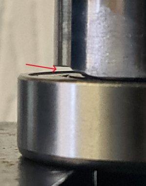
20231109_113556.jpg

It does look worse than it is; I'd say the contact area between the inner race of the new bearing and the rear of the spindle head that I've lost is not much more than 5% and the bearing is held securely in the headstock casting and there's another bearing at the rear anyway so I'm not worried. I've got the headstock back on the bed and firmly fixed down, just to have a sanity check on play and the spindle head feels firmly held when I give it a push and pull, back and forth. I also ran my 0.01mm DTI on the inner bore of the spindle and I'm seeing about 0.01mm of runout (just under really).

If my clumsiness with the grinder causes me any issues, I do still have that spindle with the too-short keyway that is, as yet, unmolested! Without a mill though I'm not convinced I can lengthen the keyway precisely enough to not end up with different issues.

Anyway, thanks for reading so far and any comments are, as always, appreciated (be gentle with me though! :D)
 
@wachuko A sad reaction to my clumsiness is kinda to be expected :D but do you have any advice/warning/general comment in regards to me not being particularly worried about this from a functional perspective.

I mean yeah, I'm a little depressed about not being careful enough to avoid damage to the rear of the spindle head when grinding but do you reckon I'm being too blithe about that damage.

One thing that did occur is the distribution of mass not being even across the spindle head now when it's spinning at speed but given the overall mass of the spindle head and chuck, I'm hoping it shouldn't cause too much uneven force on the bearings.

Whddya reckon?
 
Ah, there is one more confession to salve my 'newbie machinist's soul'.

Having used too much force to press the spindle into the installed bearing and thus shearing off that 'lip',

It does look worse than it is; I'd say the contact area between the inner race of the new bearing and the rear of the spindle head that I've lost is not much more than 5% and the bearing is held securely in the headstock casting and there's another bearing at the rear anyway so I'm not worried.
If my clumsiness with the grinder causes me any issues, I do still have that spindle with the too-short keyway that is, as yet, unmolested! Without a mill though I'm not convinced I can lengthen the keyway precisely enough to not end up with different issues.

Anyway, thanks for reading so far and any comments are, as always, appreciated (be gentle with me though! :D)
Can you shorten the key or am I missing something? not that I think you will have a problem with the spindle missing a little material, I Think it is fine.
I have separated many a stuck race using a Dremel tool. If you find yourself in this pickle again try using a cut off wheel and cutting a slot in the race. Get close and use a wedge (cold chisel or old screwdriver) to break the remaining. Races are usually hard enough to crack easily when “tapped” with a wedge and hammer. Don’t forget eye protection.
 
@wachuko A sad reaction to my clumsiness is kinda to be expected :D but do you have any advice/warning/general comment in regards to me not being particularly worried about this from a functional perspective.

I mean yeah, I'm a little depressed about not being careful enough to avoid damage to the rear of the spindle head when grinding but do you reckon I'm being too blithe about that damage.

One thing that did occur is the distribution of mass not being even across the spindle head now when it's spinning at speed but given the overall mass of the spindle head and chuck, I'm hoping it shouldn't cause too much uneven force on the bearings.

Whddya reckon?
Nothing to worry about!
 
@wachuko A sad reaction to my clumsiness is kinda to be expected :D but do you have any advice/warning/general comment in regards to me not being particularly worried about this from a functional perspective.

I mean yeah, I'm a little depressed about not being careful enough to avoid damage to the rear of the spindle head when grinding but do you reckon I'm being too blithe about that damage.

One thing that did occur is the distribution of mass not being even across the spindle head now when it's spinning at speed but given the overall mass of the spindle head and chuck, I'm hoping it shouldn't cause too much uneven force on the bearings.

Whddya reckon?

Just sorry this happened... that is all. You have a great attitude towards the situation. That is all that matters. The rest can be fixed/replaced.

Following the progress.
 
Our Aircraft Engineers would require a minimum of 80 % contact area for a locating surface to be acceptable.
 
Back
Top