- Joined
- Jul 20, 2016
- Messages
- 84
I have never been impressed with this machine. From the beginning its capabilities and abilities were rather meager IMO. After having it for a while and suffering issues with traversing to full right, I pulled the X-axis leadscrew out (my first learning experience with a mill) to discover the threads buggered up. The leadscrew was replaced, but never really solved the problems.
I discovered the excellent post here by Clif123 showing disassembled X a Y axis parts. And later in the topic, of punching out the X-axis endcap locating pins. I then did this to good, but not great, effect. So I also punched out the locating pins on the lock block, but this made adjustment even more tricky. So I reinstalled one of the lock block pins as the factory sort of peened one of the pins and the lock block. I got the full right traverse into serviceable but not great condition IMO.
I had a perception for some time that the tram was out, but had never really addressed the issue. Last week I made the simple attachment to check this and sure enough, it was out 0.005” left to right. After some time of fiddling with it, I got it with a DI (not DTI) and interpolating its readings, to; LR 0.000, LF 0.0002, RR 0.000, RF 0.000.
Now the current problem:
I have always noted some noise when milling on the edge of material (conventional not climb milling) which has increased. This has also been the case using slitting saws, and became worse in the last few days. It is a clunking or perhaps more accurately stated, knocking sound. It can be duplicated by turning the spindle back and forth by hand.
I am not very enthused about taking the machine apart. But I took off the top cover, and discovered this cover to probably be the most impressive part of the entire machine. It is a 7.718 pound iron casting with ¼ inch walls that support absolutely nothing. It could as well been a sheet metal stamping or plastic cover, and apply the weight to important parts (like I only today read, the open rear column).
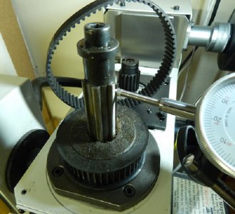
Under the cover is a rather dirty driven toothed spindle pulley and a pretty loose toothed belt. The noise I discovered by hand turning the spindle back and forth seems to be the driven pulley against a splined shaft. There is about 1/32” play (measured at the pulley perimeter) to that interface – except when the spindle is fully down.
A slitting saw test cut with the belt completely tight and the spindle fully down reveals more capability (up from 0.015” to 0.030” cut) but still some knocking, albeit less.
The mill was delivered with a very poor generic manual – not an LMS manual, and parts in the manual compared to on the LMS website requires a bit of interpretation. But the spindle pulley is $50 and the spindle is $100! But is that the problem?
Checking the bottom of the spindle runout, turning by hand showed absolutely no runout on the DI – not even a quiver of the needle. Applying force to the bottom of the spindle, in both the X and Y axis directions in turn, displays ~ 0.003” to 0.0035” each with a tenancy to hold close to half that until touched again. Applying force to the lower part of the spindle while reading the upper spline of the spindle gives about 0.004” deflection on the Y axis and about 0.005” deflection on the X axis.
Perhaps the upper ball bearing, or other bearing? Or just everything. Drawings show three bearing, all different. And are these bearings pressed on as with the mini-lathe?
Thank you, if choosing to endure this, for your patience, and any insights that may be provided.
I discovered the excellent post here by Clif123 showing disassembled X a Y axis parts. And later in the topic, of punching out the X-axis endcap locating pins. I then did this to good, but not great, effect. So I also punched out the locating pins on the lock block, but this made adjustment even more tricky. So I reinstalled one of the lock block pins as the factory sort of peened one of the pins and the lock block. I got the full right traverse into serviceable but not great condition IMO.
I had a perception for some time that the tram was out, but had never really addressed the issue. Last week I made the simple attachment to check this and sure enough, it was out 0.005” left to right. After some time of fiddling with it, I got it with a DI (not DTI) and interpolating its readings, to; LR 0.000, LF 0.0002, RR 0.000, RF 0.000.
Now the current problem:
I have always noted some noise when milling on the edge of material (conventional not climb milling) which has increased. This has also been the case using slitting saws, and became worse in the last few days. It is a clunking or perhaps more accurately stated, knocking sound. It can be duplicated by turning the spindle back and forth by hand.
I am not very enthused about taking the machine apart. But I took off the top cover, and discovered this cover to probably be the most impressive part of the entire machine. It is a 7.718 pound iron casting with ¼ inch walls that support absolutely nothing. It could as well been a sheet metal stamping or plastic cover, and apply the weight to important parts (like I only today read, the open rear column).
Under the cover is a rather dirty driven toothed spindle pulley and a pretty loose toothed belt. The noise I discovered by hand turning the spindle back and forth seems to be the driven pulley against a splined shaft. There is about 1/32” play (measured at the pulley perimeter) to that interface – except when the spindle is fully down.
A slitting saw test cut with the belt completely tight and the spindle fully down reveals more capability (up from 0.015” to 0.030” cut) but still some knocking, albeit less.
The mill was delivered with a very poor generic manual – not an LMS manual, and parts in the manual compared to on the LMS website requires a bit of interpretation. But the spindle pulley is $50 and the spindle is $100! But is that the problem?
Checking the bottom of the spindle runout, turning by hand showed absolutely no runout on the DI – not even a quiver of the needle. Applying force to the bottom of the spindle, in both the X and Y axis directions in turn, displays ~ 0.003” to 0.0035” each with a tenancy to hold close to half that until touched again. Applying force to the lower part of the spindle while reading the upper spline of the spindle gives about 0.004” deflection on the Y axis and about 0.005” deflection on the X axis.
Perhaps the upper ball bearing, or other bearing? Or just everything. Drawings show three bearing, all different. And are these bearings pressed on as with the mini-lathe?
Thank you, if choosing to endure this, for your patience, and any insights that may be provided.