My PM 1440GT

Nice report on setting up your lathe. Just wanted to add that I don't know of any seller that adjusts and certifies the headstock alignment before shipping. Might be one out there but I think they assume you will do the basic adjustments yourself - align the headstock, level the lathe and align the tailstock.

The next time you check your headstock alignment, I suggest you use a shorter rod; about 4-6" stick out of 1 to 1.5" stock is fine. If stick out is too long then you're dealing with material deflection, especially when using inserts. It might not be a bad idea to grind or have ground for you a good HSS tool bit just for doing test cuts (headstock alignment, 2-collar tests); it will give you the most accurate test cuts with minimal deflection. When a hobby guy is shooting in the tenths on these kinds of tests a good cutting tool makes a difference.

I assume you leveled the lathe with a 2-collar test before aligning the headstock. You might want to do a 2-collar test again to confirm the lathe is level because the order in which alignment procedures are done makes a difference, at least in my experience. I have found that it works best for me if I align the headstock first, then level the lathe, then align the tailstock last. All this is done with test cuts on the lathe, not with manufactured bars done by others.

Again, you did a great job setting up your new lathe. Having guys like Mark Jacobs and David Best in your corner is a major advantage!

Welcome to HM!
 
Mikey makes an excellent point about the stick-out. Tool pressure alone will often account for 3/10th deflection with 9" of stick-out on the part. In addition to shortening the stick-out, here are some other ideas that might help getting to a more precise alignment check.
  • If you are using insert tooling for the cutting operation: Pick an indexable tool that has a neutral or positive rake angle and an insert with a sharp cutting edge. This will lower radial tool pressures. Make sure the depth of cut is at least 1/2 the nose radius of the particular insert you're using. If the DOC isn't deep enough, the majority of the pressure between the tool and the part is radial - pushing the tool toward the tool post and the part in the opposite direction. By setting the cutting depth to at least 1/2 the nose radius, the pressures shift axially - toward the chuck, and deflection is reduced.
  • Do as much as you can to increase rigidity: Pull the compound back so the tool post is directly over the compound swivel base, and not hung out in a cantilevered position. Turn the compound so it is perpendicular to the work piece, and make sure the compound locking screws are tight. Choke up on the tool.
 
Last edited:
Thanks to everyone for the suggestions and encouragement, that's what's great about being here everyone is helpful.
 
Rifleman:
I have a similar lathe, an Eisen 1440E. Like you, mine needs to have some risers built. I was planning on welding up some but I noticed yours have some horizontal bolts right above where the vertical adjustment bolts are. What are they for?
 
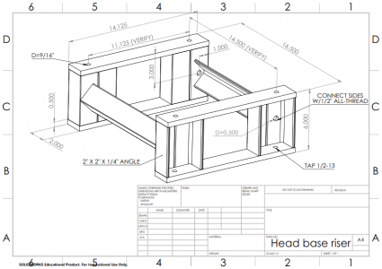
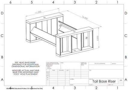
Those are to ensure rigidity and to link them together. I have to say I got some of the measurements and the idea from JBOLT's PM 1440GT. The top plate is 2" wide 1/2 thick. It would be easier but more costly to use C channel but these are using 2X2X 1/4 angle iron 5" long resulting in 6" of height. I'll say they came out the perfect height and are very sturdy, rigid.
 
After looking closer, I now now see that that is just a rod between the two risers. Gotcha.
I was planning on making a "box" for each end of my lathe that runs the full width of the machine. I am slightly concerned though about introducing any twist but I am thinking that the bolts on the cast iron pads will take any twist out.
This is probably a next winter project unless I find a day that I don't know what else to do (hahaha).
These are the drawings for the risers I sent Rifleman1384.

It was based on stock I had on hand.

I wasn't sure how flat the machine bases were so I used all-thread to clamp a piece of angle between the front and back of the riser to allow for some 'float' instead of welding. I could have pre-fitted and tacked them but I was in a hurry (i.e. lazy) and didn't to deal with on-tack-off-weld-paint-on.

Head base riser_001.pngTail Base Riser_001.png
 
Rifleman: “Everything went well I thought, the only thing that was not doable was my request to have my machine built with a spider already in the spindle”

Rifleman, congratulations on you new lathe! She’s a beauty; I am sure you will have many enjoyable hours setting-up and using your new lathe.

I have a 1236-T and installed a hand wheel and later a spider. If you search something like, “Setting up the PM 1236-T” here on the forum and look at the posts starting at 117 and then 192 you will see one way of doing a hand wheel and spider. I would insert a link directly to it if I knew how.

I use the hand wheel all the time; it is much easier than trying to grab the chuck to rotate the spindle and have gotten into the habit of rotating the spindle using the hand wheel just before turning the lathe on to make sure everything is clear. I would really miss not having it.

Again, congratulations!


B75E5A1A-C04E-4B92-9E88-16BD5B0BA04A.jpeg
E98FDE7B-8206-4A87-BB87-9E4E7B44D4E8.jpeg


106E24BD-6C4F-464D-A283-50A82115FB97.jpeg
 
Back
Top