Mystery Lathe Help

NorthernCræft

Registered
Registered
Joined
Feb 21, 2021
Messages
10
Hello!
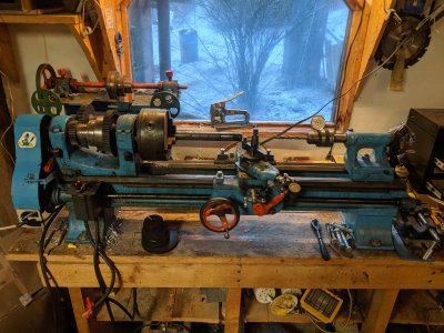
I am a total beginner when it comes to machining but it is something that I have an inexorable draw towards so I was keeping my eyes open for a cheap middling size lathe. I picked this one up in Canada on my way north to Alaska for 500$ it came with a plastic tote full of tooling and various calipers etc which I haven't yet fully gone through. I've done a little bit of turning on it, made a few components for other projects out of aluminum and plastic, most notably spring loaded nozzle for a pressurized wax injector for lost wax casting. The learning curve has been steep, watching well edited youtube videos of machinist who know their craft made it look easy and I am finding my skills are a far cry from polished. But I certainly have some questions.

First: Does anyone know what kind of lathe this is, I can find no names anywhere on it except for on the forward reverse switch but that is just for the switch. I am hoping if I can find a name it will hone my search for answers, maybe its shop built? The guy I bought it from was selling it for his son who was out in an oil camp. See attached pictures

Second: I am wanting to try my hand at threading and need some help making sense of the attached chart and how to match it to the gears on the lathe.

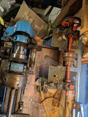
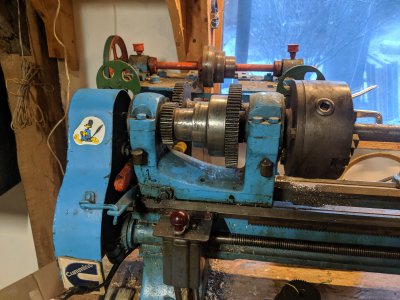
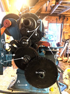
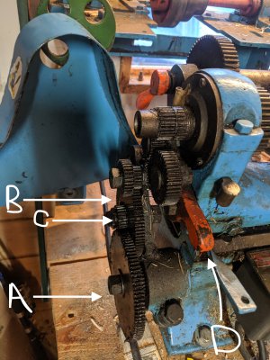
As far as I have been able to figure, the gear marked std is the stud, C & B are the idler and A is the screw (obviously). The spindle is at the top, is there a name for the two gears following (or preceding? Does one start at the screw gear or the spindle when describing the change gear train?) the spindle and before the stud? Im not sure if it is helpful but the gear train that is shown in the pictures is as follows starting at the screw and working towards the stud: Screw: 100 teeth, Small Idler: 24, Lrg Idler: 80, Small std: 16, Lrg std: 24, Unnamed gears: 44, 28, Spindle: 24.
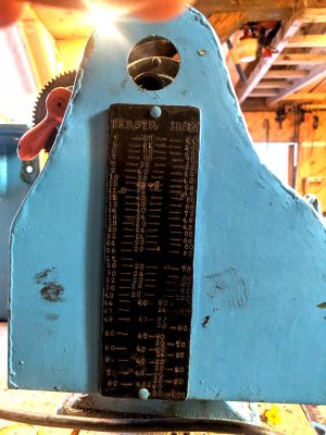
Looking to the chart attached to the gear train cover its shows what I assume to be threads per inch (THD). Stud (STD) Idler (ID) and Screw (SCW). But the idler, and stud have multiple (compound?) gears and the chart only shows one number. How do I read this chart? and seeing as I got this in canada can anyone tell by looking at the numbers if this is for Metric or Imperial? The change gears are stamped with number of teeth not mod whatever which as i understand is the metric convention for gears? I have a small stack of additional gears shown in picture 1, I don't have them in front of me but as I recall the smallest was 45 teeth and the largest was 90 teeth, I will post the exact gears and the dimensions if that is helpful.

Well I know that was a lot of questions all jumbled up but any insight would be helpful and I thank you for your taking the time to read through this.
 

Attachments

  • IMG_20191223_152144.jpg
    IMG_20191223_152144.jpg
    4.2 MB · Views: 173
  • IMG_20191223_152238.jpg
    IMG_20191223_152238.jpg
    4.2 MB · Views: 167
  • IMG_20191223_152159.jpg
    IMG_20191223_152159.jpg
    3.8 MB · Views: 131
  • IMG_20191223_152321.jpg
    IMG_20191223_152321.jpg
    4.8 MB · Views: 120
  • IMG_20191223_152330.jpg
    IMG_20191223_152330.jpg
    3.6 MB · Views: 124
  • IMG_20191223_152314.jpg
    IMG_20191223_152314.jpg
    3.7 MB · Views: 181
The gears that are on the machine will control the distance the cutting tool moves per revolution of the chuck. There may be levers on the saddle that modify that, or there may not. In any case, only one thread series 8-16-32 or 12-24-48, or some such is possible with one set of gears.. There may be another lever (on the carriage) that selects thousandths per revolution, .002-.004-.008 or some such. You will need other gears to change these numbers, that 's what the chart on the end tells you. (I see you do have other gears, I hope someone can shed more light on the lathe.
The shape of the orange handle on the carriage is remeiscent of a lathe I operated at one time, but of course I can't remember what it was.
 
Last edited:
I think you might be right about the clone, it does look very similar to the 405 you linked especially the tailstock, perhaps they even just got some parts from an old southbend then built it as the bed and the bed supports don't look as polished as a production unit. But that definitely got me in the right direction the "compound-reduction changewheels" of the 405 you linked appear to be set up exactly the same. and with a little googling found an answer to part of my question: the names of the two gears between the spindle and the stud: tumble gears. The more you know..

I would agree the gear cover and chart are definitely homemade as is the bracket that hold the stepped pulley behind the lathe in the first picture.
 
The gears that are on the machine will control the distance the cutting tool moves per revolution of the chuck. There may be levers on the saddle that modify that, or there may not. In any case, only one thread series 8-16-32 or 12-24-48, or some such is possible with one set of gears.. There may be another lever (on the carriage) that selects thousandths per revolution, .002-.004-.008 or some such. You will need other gears to change these numbers, that 's what the chart on the end tells you. (I see you do have other gears, I hope someone can shed more light on the lathe.
The shape of the orange handle on the carriage is remeiscent of a lathe I operated at one time, but of course I can't remember what it was.
When you say 8-16-32 and 12-24-48 are you referring to gears in the change gear train or threads per inch? and if the later is the case would you be willing to expand upon that? As I understood it to change the number of TPI one would change the gears in the train(is train the correct term to use in this case?). On my Saddle there is the lever to engage the half nut, a threading dial and the handwheel.
 
Nothing about this lathe suggests to me that SB had anything to do with it, especially the large diameter spindle bearing housings, the front with 4 bolts, they look like they possibly house anti friction bearings; no older SB lathes looked like that.
 
Doesn’t look like a South Bend. Every workshop/9” SB I’ve seen has only one bolt for the headstock bearings. Some of the older early models had a cap with two bolts. That one has two for the rear and four for the front. Never seen that on a SB. I suspect a clone also. That brass tag looks like it was shop made.
 
Heck.... read this. You might have one of his earlier castings
Your compound and cross slide dials look eerily similar.


lathes.co.uk
Lathe by C.Hansen of Winnipeg


Though to have been made in small numbers, this finely constructed little 4" x 20" backgeared and screwcutting lathe is believed to one of a several different designs by Mr. Carl Hansen, once the foreman of the machine shop at MacDonald Brothers Aircraft Company in Winnipeg. The Macdonald Company later became part of Bristol Aerospace before finally being bought by Rolls-Royce. Looking to have been inspired by an early South Bend lathe of a similar size, the lathe was built using castings poured just before WW2 with machining work carried out after hostilities ceased. In 1954 the lathe passed into the hands of the head of MacDonald's R & D department and from there, eventually, to his son, from whom the present owner purchased the machine. The vendor reported that Carl had also built other designs of lathe with 4.5 and 7-inch centre heights around the same time - as well as violins and grandfather clocks and so appears to have been both a machine-tool builder and keen model engineer. In a 1932 edition of the Winnipeg Free Press some evidence of his work survives - he is mentioned as having displayed a recently-finished 4-inch centre lathe at a local model-engineering society show. Fitted with a 3-speed flat-belt drive to the headstock spindle, like most early and lighter South Bend lathes, the motor now used carries a V-pulley with the V-belt wrapped (very effectively) around a single flat crowned pulley on the countershaft. Fitted with a long, 1.2" x 10 t.p.i. threaded nose backed by a plain register bored with a No. 3 Morse taper socket, the headstock spindle ran in bronze half-shell bearings with the slow-speed backgear having to be engaged by first slacking a nut (instead of a quick-action spring-loaded pull and twist pin) on the face of the large spindle-mounted bull wheel. Sturdily built, the compound slide rest assembly had a cross-slide screw fitted with a small but crisply-engraved micrometer dial, this having, just outboard of it, a neatly arranged, narrow grip-ring knurled on its outer surface. Unfortunately, the top slide had no micrometer dial, though the periphery of its base was marked with a degree ring to indicate the swivel angle. It appears that this lathe never had the test run that would have enabled the marking of a matching zero line on the cross slide casting. Driving through a tumble reverse mechanism - unlocked by a lever rather than an inconvenient nut - screwcutting to the Acme-form, 8 t.p.i. leadscrew was by changewheels, of which it appears that the usual set of thirteen was supplied. Able to be offset for the turning of slide tapers on V-ways, the tailstock had a No. 2 Morse taper spindle with around three inches of travel, this being locked by a proper "split-barrel" compression mechanism rather than the cheap and nasty way of a slot cut into the casting and closed down by a stud and nut. The owner of the lathe reports that it displays an excellent cosmetic finish, is rigid, very accurate and capable of high-precision work. If you have a lathe or other machine tool, or a model by Mr. Hansen, the writer - and the owner of this lathe - would be pleased to hear from you.
If you have a lathe or other machine tool, or a model by Mr. Hansen, the writer - and the owner of this lathe - would be pleased to hear from you.


your tailstock even looks like it has a screw at the bottom which looks for some sort of taper adjusting ?
 
Last edited:
When you say 8-16-32 and 12-24-48 are you referring to gears in the change gear train or threads per inch? and if the later is the case would you be willing to expand upon that? As I understood it to change the number of TPI one would change the gears in the train(is train the correct term to use in this case?). On my Saddle there is the lever to engage the half nut, a threading dial and the handwheel.
Modern lathes have a lever on the face of the head which will switch internallky in the head, between multiples, 1, 2 and 4. thus the numbers in my post. I don't see that arrangement on your lathe. so disregard them. Yes, to both, Referring to threads per inch and feed in thousands per inch. In that case there are levers on the compound to control longitudinal and cross feed. Your lathe lacks them. So. only by chaning the gears on the end can you change how you cut. I was attempting to give you background on the gearing, I cannot make out what the gearing panel says, (old eyes, I guess). I would suggest mounting an indicator on the bed, reading the movement of the saddle, record how the saddle moves for one revolution of the chuck, and keep switching gears usntil you have a list of gears and their effects. I would expect that you need many more gears than you seem to have. Perhaps the meaning of the chart will become clear. Good luck, keep playing with it, machine work is a reward itself.
 
@NorthernCræft ,

Working out the entire gearing is NOT rocket science.
I did it for my first lathe as I had no charts.
For my current Southbend 9" I did it just to understand it all......and fill in some gaps on the chart.

You will need to know:
  1. the tooth count of every gear in the train (including the spindle gear)
  2. the layout of the gears (simple vs compound, as the math is slightly different)
  3. the lead-screw pitch
  4. the tooth count of all the spare gears that can be swapped in

I am currently working on a document about lathe gearing, sort of "getting started" tutorial.
I am also trying to come up with a spreadsheet to organize and automate the calculations.
But those won't be finished for a couple weeks yet......

-brino
 
Back
Top