Needing more than a spark test?

I'm chagrined to report I made a dumb-ass math error in my attenuation calculation for a .25" thick aluminum plate. The absorption factors are all in centimeters, but I used the thickness in mm. Duh. So instead of just 1% of the primary gammas getting through, it's 60%. No wonder my detector was outputting pulses in the absence of a "real" sample.

It's definitely time to get out that sheet of lead I got awhile back! I have more on order, too. Even a 1/16" layer reduces the gamma flux by a factor of .0001 times. And I DID get the units right this time :)

So for any other folks who have a number of little disks of Am241 lying around, take heed and don't depend on an aluminum enclosure to keep all the gammas inside. Right? Right!
 
On the quiet regulator front, the usual 78 and 79 regulators are kind of short of gain at switch frequencies, and dont do s good job attenuating them.
Start with a dumb transformer/rectifier/capacitor if you want quiet! Then regulate...

Sent from my SM-G892A using Tapatalk
 
On the quiet regulator front, the usual 78 and 79 regulators are kind of short of gain at switch frequencies, and dont do s good job attenuating them.
Start with a dumb transformer/rectifier/capacitor if you want quiet! Then regulate...

Sent from my SM-G892A using Tapatalk
You are so right about 78 and 79 regulators. They may linear regulate, but they rely on downstream capacitors to deliver transient currents.

Re: transformer, rectifier, etc. Yes indeed, except for me, the transformer is a tiny thing in a ferrite pot core, and the AC frequency is MHz, and the noise filter is not just a storage capacitor that will ripple as it delivers energy. The key thing is that the energy is transferred magnetically across a transformer, so the 0V from the secondary side is isolated, and can be used, pristine-clean.

Then, using one of the ultra low noise op-amps, with GHz gain-bandwidth product, we use it for a uncompromising regulator where we need to.
 
Even a 1/16" layer reduces the gamma flux by a factor of 0.0001 10,000 :)
You were not really wrong - this is about UK cultural semantics!

I do that all the time :( , only much worse! On this forum, the demographic is such that inches are widely used, and I slip up between using 2.54 (for cm) and 25.4 (for mm). I mess up on mils, and mills and microns and "thous", and "tenths", and millionths. I have had to surrepticiously edit postings before someone called me out on it.

One thing I can't really relate to is Fahrenheit degrees. I have a little calculator app that subtracts 32, and then does x 5/9. I think the reason there is 180 degrees between freezing and boiling might be because the guy couldn't afford another instrument maker, so he re-purposed a school protractor! - maybe :)
 
Last edited:
One thing I can't really relate to is Fahrenheit degrees. I have a little calculator app that subtracts 32, and then does x 5/9. I think the reason there is 180 degrees between freezing and boiling might be because the guy couldn't afford another instrument maker, so he re-purposed a school protractor! - maybe :)
The origins of the Fahrenheit scale are a mite peculiar by today's standards. 0F was defined by the freezing point of a particular brine solution, and 100F was defined by some mythical human's body temperature. Nowadays it, like Centigrade, is based on 32F being the freezing point of water and 212 being the boiling point. Of water, not a human being :)

On the other hand, while 0C is pretty well defined by the freezing point of pure, gas-free water, the boiling point depends on the altitude. So there could have been some variation for 100C....at least, until someone figured out the altitude thing.

Then there's the Kelvin scale. 0 Kelvin is unreachable, and the step size is the same as the Centigrade scale.

I loved one of the sentences in the Wikipedia article regarding the origin of the Fahrenheit scale: "In the United Kingdom, degrees Fahrenheit figures are sometimes used in newspaper headlines to sensationalize heatwaves."

Back to XRF, I think I don't need to add a sixth connection to my DIN connector. The pocketgeiger design makes it easy to use an external bias voltage in place of the switcher-generated voltage, and the on-board LDO can still be used to run the amplifiers. I'll mark up a schematic and attach it to another post to show how that can work.
 
I've attached a marked-up copy of the PocketGeiger schematic. The +10 supply voltage is the same voltage used for my signal-conditioning board, so that frees up the connector pin formerly used to run all of the pocketgeiger circuitry. The switcher is removed, but the +10 still has a path through the inductor and a Schottky diode to get to the LDO regulator. This gets the amplifiers up and running. BTW, I swapped out the LMC662 for a different amplifier, which has a maximum 5V supply limit so the LDO also was replaced with a 5V version. As a result it has plenty of headroom to operate.

The connector pin that WAS used to run the pocketgeiger now can be repurposed as the diode bias-voltage input. I'm leaving the low-pass filter network in place, to ease the requirements on the bias voltage supply.

In addition to getting rid of the switcher noise, now I can experiment with varying the bias voltage. Oh boy, another knob to tweak :)
 

Attachments

  • PocketGeiger ext bias V.pdf
    303.5 KB · Views: 6
This week has been sort of a "snow week" so I had some time to work on a number of project, including the XRF system. Regarding the latter, I modified my PocketGeiger board per the scheme I outlined in message #616, immediately preceding this one. I double and triple-checked the connections because connecting +26V to the wrong place would definitely cause some damage. I still need to make a lead shield to isolate the detector from the back-emitted gammas from my Am241 capsules, but my setup was complete enough to check the system noise and capture some background pulses due to cosmic rays and random counts from the environment.

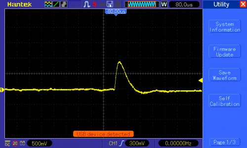
Here's a pulse showing that the boost switching regulator noise has been eliminated. The baseline noise level isn't too bad, either. For the first time in quite awhile I'm more optimistic than pessimistic regarding the diode detector as a viable proportional detector.

XRF_background..jpg

The signal amplitude isn't too bad, either: the above waveform was acquired with my signal-conditioning board's X1 gain setting. It's clear that the X100 gain setting won't be usable, but that's OK -- the gain settings were a shot in the dark anyway! The pulse shown isn't the largest, nor the smallest I've captured so far, but I don't know what pulse amplitudes I'll get from iron, cobalt, nickel etc. Hopefully that WILL be known pretty soon!

FWIW, I haven't altered the the PocketGeiger's analog signal chain other than replacing the amplifiers, so its frequency response is unaltered from a stock unit.....aside from any considerations regarding possible differences in the amplifier's GBW product.
 
I wasn't clear in my previous post that my Am241 sources were NOT in the box. So the only counts were from background radiation.
 
Also FWIW, I didn't observe a substantial difference in the baseline noise level when I varied the detector bias voltage from 10V to 25V. This is an interesting result, suggesting the main contribution to noise is NOT the detector's dark current, since it should change quite a bit between 10 and 25V. I haven't characterized the detector's sensitivity vs. bias voltage, either.

I suspect the detector sensitivity won't change much, as long as the applied bias voltage is enough to sweep the generated carriers out of the PIN junction before many of them recombine. I should see what a zero-volt bias does, I guess; but I really need a known elemental sample to do this kind of characterization. Looking at random background pulses is an exercise in futility in this regard.

Setting the trigger source to the AC mains didn't reveal much, if any, 60Hz noise. With .25 inch-thick walls, my enclosure should be able to keep out a lot of 60Hz mag-field noise in addition to all of the E-field noise, so no surprise there.
 
  • Like
Reactions: rwm
Also FWIW, I didn't observe a substantial difference in the baseline noise level when I varied the detector bias voltage from 10V to 25V. This is an interesting result, suggesting the main contribution to noise is NOT the detector's dark current, since it should change quite a bit between 10 and 25V. I haven't characterized the detector's sensitivity vs. bias voltage, either.

I suspect the detector sensitivity won't change much, as long as the applied bias voltage is enough to sweep the generated carriers out of the PIN junction before many of them recombine. I should see what a zero-volt bias does, I guess; but I really need a known elemental sample to do this kind of characterization. Looking at random background pulses is an exercise in futility in this regard.

Setting the trigger source to the AC mains didn't reveal much, if any, 60Hz noise. With .25 inch-thick walls, my enclosure should be able to keep out a lot of 60Hz mag-field noise in addition to all of the E-field noise, so no surprise there.
Yes - just maybe.. and I say if it works, it works, then go for it!
I do love the pulse you have. I bet you had a bit of a "celebration"!

Indulging my deeper thoughts..
Carefully considered, I still think we only know where where we are when we can distinguish, and even perhaps measure, the dark current, and hence know the smallest energy which photons we might have an interest in would have to exceed, just to make themselves known. The dream wish is to see the contribution from Carbon, which would make a current of the same order as the diode noise when biased around 2V. [Carbon Kα1 = 0.3KeV]. Going for 2V bias comes at the cost of a whole 150pF to be charged and discharged, which would become the dominant "component" of what determines the pulse shape. This is assuming the other parts of the amplifier circuit do not also limit the response as to mask it.

10V bias drops the capacitance to 80pF, but raises the dark current to about 2nA. This is only worth doing if the bandwidth of the amplifier can benefit from it. For detecting the lower energies, perhaps 3V is a reasonable compromise. Zero bias puts the dark current at 600pA, but with a madly large capacitance of about 0.5nF in shunt. In a high impedance circuit like this, that is almost a "smoothing capacitor". We have to wonder whether we still believe the content of any pulses produced.

You still have the Pocket-Geiger circuit as a test-bed, although having changed the op-amp. One would hope to see the total of all known noise currents that really do have to be there. If the noise figure of the entire front end transconductance amplifier is higher than the diode dark current noise, you would simply not see the dark current, which is not the same thing as finding it to be insignificant. If it sticks up more than about 2dB above the racket, we can get at it. The key thing is, not to make extra racket! Changing the feedback resistor to something much lower, and then piling on the gain in later stages, should tell you something, even if some of that gain is in the oscilloscope front end.

One thing I am not entirely clear on. When we see the value of "Dark current" plotted vs Reverse Bias in the X100-7 specification, is that a all a DC current? If it is, then we have to separate the DC from the noise component in the spec. We can somewhat bias away to reduce the capacitance, knowing that the noisy current is 6.1e-14 A/√Hz. That spec is for 12V bias. For 250kHz bandwidth, this makes about 15nA, which is somewhat too high. This is why I think 3V bias is better, or 2V if we can get away with it, and have an amplifier that won't spoil it.

Theoretically, the currents into the transconductance amplifier might be:
1. The thermal noise in the molecules bashing about in the first gain stage semiconductor within the op-amp itself - ie. it's own noise figure.
2. The noise going into the amplifier input via the feedback resistor - figure 4kTBR.
3. The noise already present on the injected bias current, added to the diode dark current noise.
4. Finally, the "noise" we do want to see - that of carriers provoked into conduction by a photon.

--------------------------------------
Not to misunderstand.. take all the stuff above as just one's passing thoughts when messing with this thing, and I do get it that we are not designing an instrumentation module for NASA to place on Mars. It may be that all of those niceties listed above are out of reach for us, but we can still get meaningful useful amplitude and duration pulses out of a practical test getup!

I think I may be just about as stoked about this result as you are! :)
 
Last edited:
Back
Top