Needing more than a spark test?

I am getting excited about building one of these! After you guys do all the heavy lifting of course. I am still curious whether solid state or PMT is the best route. I would say if the diode can be made to work with the required spectral resolution it would be the winner.
R
 
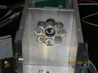
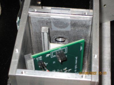
I have attached a couple of photos showing my XRF setup. One is from the source side that faces the sample we want to analyze. The second is taken from the detector side. The photos were taken at about a 45 degree angle down from horizontal, and that's why the source-side photo doesn't show the detector. I used a flashlight to double-check the position of the detector relative to the aperture hole, and it does line up.

XRF source side.JPG
XRF detector side.JPG

Also, I turned the source-side around to face the detector, in order to determine what the pulse height and the count rate are. The pulse height is around 15 millivolts, low for sure -- but that's expected since 60Kev efficiency is just 3%. Back-calculating the pulse height for a 100% efficiency pulse, we get about half a volt. OK, not too bad.

The next thing I did was to try to estimate the count rate. Since radioactive decay is a random event there was a wide variation, but I'm guesstimating anywhere from 40-70 counts per second. This seems really low, given the 8 sources, each producing about .8 microCuries, roughly 30KBq. But let's check that out. The sources were placed about 5 inches away from the detector, so the surface area of a sphere with a diameter of 254mm is 202682mm^2. The detector is 100mm^2, so it should intercept about .0055 of the total photons emitted by the sources (240KBq, assuming about .8 uC/source). Therefore the detector should see something on the order of 1500 counts/second. That's quite a difference from what I'm seeing. Now I'm wondering (again) about the REAL activity of the sources I bought!
 
Great pictures Mark :)

About the only way the real activity of the sources you bought could be changed for the worse is if the amount of Am241 in them was reduced. Given the way these things are made, the cost of a "feeble" product would not be significantly different. To get smoke detectors to work, they need enough alpha ionizations to make a current through the air space in the chamber.

For almost all, it is 0.25micrograms, to 0.29 micrograms. The decay events rate in a 0.29 microgram version is 37,000 Bq.
As I understand it, every decay is accompanied by a set of photons, including the 60keV Gamma.
Within the diode material, the photon can miss the atomic cross-section entirely, or it might get to do it's photoelectric effect.

Where we are at odds here is about the 3%. Truly, the height the pulses you see are not altered at all by that. It is the NUMBER of them.
Expect that the probability of a diode response is 0.03 for the 60keV photons. It can be a full height big pulse, but fewer - not so often.
Then that, multiplied by the solid angle fraction of the sphere, which you have as 0.0055. So 0.03 x 0.0055 => 0.000165
This alone brings the count rate to 6.105 per source (of the 60keV type, and also the 1.5keV type, if there were any).
With eight of them, you might get a total of 48 per second.
There will be others, maybe some much bigger, but not from the sources.

The up and then down shape of the absorption probability curve only means that after one has the collection of counts, then one needs to divide by the probability corresponding to the energy of the bucket, to scale the value to properly represent the count that would have happened if the chances of catching all energy photons were equal. In effect, compensation to "level out" the curve.

The calibration to set a pulse height as belonging to a (say) 60keV photon is a post-processing thing. Thankfully, the pulse height vs photon energy relationship is directly proportional, in the linear range of an amplifier.

I am thinking your test setup is pretty uncompromising when it comes to excluding unwanted stuff.
It looks like your sources are still set in the ring of the ion chambers - I think.
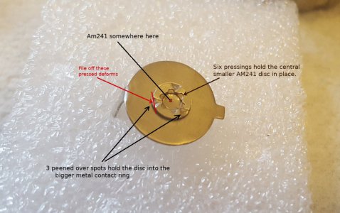
I envisaged a much smaller arrangement, with the source discs removed from all the surrounding mounting and ion chamber connection metal
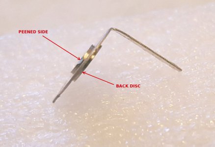
bits. To get them free, I had to file off the pressed peenings, so I could push them back from the ion chamber connection tag metal.

I had planned to place them in a close crowd, around the diode, but shielded, and unable to irradiate the diode directly.
For a radiation diode test, I think I might have temporarily taped or stuck some directly onto the face of the diode, or put a set of them together on the end of a aluminum test tab wand, all pointing the same way. For any who pick up on this thread late, I include pictures of how I got at the sources.
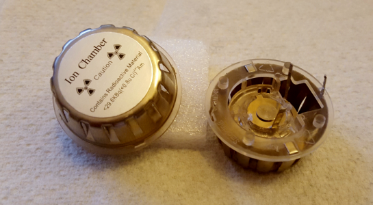
Am241 Smoke Ion Chambers.png

Am241 Smoke Detector Source1a.jpg

Am241 Smoke Detector Source2.jpg
 
Last edited:
I have come around to agreeing with @graham-xrf 's comments regarding absorption probability, since his numbers are pretty consistent with my observations. Thanks for the correction!

There is yet another statistical issue that acts to further reduce the count rate for the XRF photons, and that is the large difference between absorption in the 6Kev range (stuff from the sample) and the 60Kev primary photons. Looking at iron, for instance, its u/p value is 84.4 at 6Kev and only 1.2 @60Kev. So for the sample photons, 99% of them come from just the first 70 microns of iron -- anything emitted deeper than that is absorbed on the way back out. But only 4% of the 60Kev photons are absorbed in 70 microns. And it gets worse. Of the 6Kev photons, only a fraction of them are intercepted by the detector. So the count statistics are pretty low in that regard, as well. To improve things as much as possible, it appears we want to accomplish two things:

1. Minimize the distance between the 60Kev sources and sample; and
2. Minimize the distance between the irradiated part of the sample and detector.

The simplest way to get both is to have the sources and detector facing each other, with a thin sheet of the sample in between them. A 1mm thick sample of a ferrous alloy will absorb all but 39% of the primary photons, but this approach would allow us to place the sample very close to the detector.

Second-best might be a cylindrical arrangement of sources with the sample and detector placed along the central axis -- in this arrangement, we should be able to maximize the incident 60Kev flux on a sample and get the detector pretty close to the sample as well.

The fact that the silicon detector is only going to pick up about 3% of the primary photons can actually be used to advantage in these kinds of geometries. Unlike a scintillator-based XRF system. We might have a "lemon" of a detector so let's make lemonade!

The alternative would be to stick with the geometry that is used by the Theremino and Open Physics Lab folks and content ourselves with waiting a very long time to get decent spectra. This approach would be most compatible with the "analyzer gun" style of XRF system, but holding it on the target for hours at a time would get pretty tiring. However, I think their design could likely be optimized to take advantage of our detector's low count rate at 60Kev. Graham's approach of removing all but the active part of the source would be a good step in that direction -- but it may not be necessary to go quite that far. Just trim off one side of each so they can be moved in closer to the detector -- it doesn't matter if the larger parts overlap, as long as the little Americium-impregnated disk isn't covered.

Also, I've been thinking about Graham's idea of canting each source over to point to a "focus". If the sources were a point source this wouldn't buy us anything, but that isn't the case. See here for what I mean. In addition, as the relative angle between the plane of the source and observer increases, the effective size of the source decreases, becoming more and more point-like so the 1/r^2 factor does finally kick in. The bottom line is, I think that directly aiming the sources at the sample volume will produce an improvement in the incident flux of 60Kev x-rays.

My first/simplest alternative geometry will be fairly easy to try on my current setup, at least with a little bit of futzing around. Well worth trying, anyway -- viewing it with the Edison approach in mind :)
 
We progress :)
I entirely agree about getting up close!

I do not believe that one need wait more than a couple of minutes to gather enough pulses for an identification. 10 seconds would be convenient. 4 minutes would test my patience. Realistic discoveries might require it hang about for more than that, but if so, I would be looking to have it speeded up somehow.

I don't think that the pocket-geiger has anything more to teach us. There are no suitable words to express the feelings I got when we picked apart all aspects of the pocket-geiger design. Ever deepening profound disappointment as more and more of what it was, what it did, and how it did it, was revealed in the tear-down. The one bright thing there was we had found an alternative detector that did not need high voltages.

On the subject of detectors, over time, we might still be on the look-out for others. We know that anything with rare earth transition metals in them are good at it. Tellurium, Cadmium, Selenium, Germanium, and generally most stuff that has been tried in photocathodes are likely to be good. We still want a low cost, convenient, effective X-ray detector. We have settled on radioactive smoke detector sources to try and make this work, and that is probably the smart choice. The problem is, regardless the source is harmless provided you don't eat it, there is still pressure to use "other" smoke detector methods.

Re: My first sources arrangement
I do agree that pointing the source into a foil, with the detector the other side, could be a good way. That is how Rutherford discovered that his sheet of gold was mostly empty space, because the distance between gold atoms was about 8000 atoms-widths apart. For all sorts of reasons, I go with the back-scatter method. So long as your iron sample, or whatever is thicker than about 5 tenths, what comes back will be satisfactory. At this point, (and my apologies for being nit-picky here), I think if any 6keV photons arrive at the diode, the fraction intercepted will be about 95%.

I do like (and want), the lemon detector. :) The thing is, photons can be diffracted a little, but will not go around corners, and 60keV photons have a wavelength so small, they won't get reflected. Instead, they go way deep into the atomic lattice, and whack on electron probability wave function stuff. We don't get even the 3% of 60keV back to the detector diode. We should get zero!
A small sample can be tested by putting it down on aluminium foil. Larger stuff is just by putting the assembly up against the thing being tested, or cutting a "window" into the foil, to get at rods and bars.

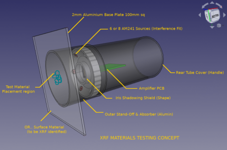
For convenience, I post the picture again here.
XRF Sources & Sensor Concept.png

The "tilting" was conceived to minimize the wasted photons trying to excite against the lead wall. It has been pointed out to me that if the sources were all just simply pointing forward, and not at all down a shielding hole, then so long as there was a "ring" of lead surrounding the diode, no 60keV could make it to the diode, and we would still have a maximum irradiation of the sample. The winning comment was that it would also them be way easier to make! Still, I liked my superglue optimum angles mounting, BUT, as was also pointed out, all extraneous substances in there are "noise". So - interference pressed in, or punch-peened, or something, but no glue! Making parts of lead is a bit awkward, but most places we can use aluminium, and line with lead where we need to.

You progress really is motivating me to move my XRF on. Sadly, today was spent putting doing work on the house, and there is a whole lot yet to do!
 
Last edited:
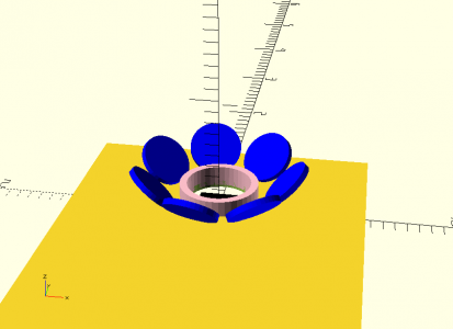
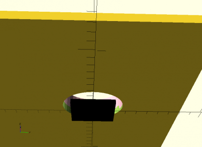
I've done some "sketching" using OpenSCAD to see how much the geometry of our source/sample/detector can be improved, using some of the ideas I presented in my previous post. I've attached a couple of renderings. The renderings are to scale:

View from the source side:

XRF sources and shield A.png

And from the detector side, showing that the shield ring around the aperture completely blocks the primary x-rays:
XRF sources and shield B.png
If I'm reading the scale right, the sample can be placed about 1/2 inch above the source plate for maximum 60Kev illumination. In this rendering, the detector is 1mm below the aperture plate, which is a .0625 inch thick lead plate (about 1.5mm thick) The shielding ring also is formed from 1.5mm thick lead. The sources are tipped at a 45 degree angle, which causes a small amount of shadowing due to the shield ring. I think a higher angle will require a taller shield ring, which will block more 60Kev gammas so 45 degrees may be about optimal. There is some interaction between the source tilt angle and how far away they have to be placed above the aperture plate (to avoid mechanical interference). But if folks want to play around with the geometry, let me know and I will upload the OpenSCAD script. No, the comments aren't real great but OpenSCAD runs so fast that it's easy to see how the geometry changes as you mess with angles etc.
 
After a bit more refinement, mostly to reflect a better measurement of the smaller Am241-laden disk, it appears that a 45 degree tilt of the sources (and attendant tweaks to the lead ring around the aperture) won't prevent many, if any, of the 60Kev gammas from striking the sample.

I've attached the OpenSCAD script I've written to explore the geometry.
Hmph, it appears that this forum doesn't want folks to attach .scad files. So I renamed it to .txt -- just download it and rename it back and you're good to go. So much for anti-virus paranoia :)
 

Attachments

  • XRF emitters.txt
    1.3 KB · Views: 2
  • Love
Reactions: rwm
Firstly - about not being able to share OpenSCAD model .scad files. I think we should resort to @vtcnc with "please help us out here"!
It's OK to download a .scad file with extension .txt, because it really is a text file, and would not cause any problems to anyone opening it. They just get to see text. I have not used OpenSCAD before, but it is in the repository, version 2019.05, so I installed it.

1/2 inch is getting right up close, but I think you are right in the approach. I did wonder if one can get "too many" pulses?
Thinks..
Provided there is no "pulse stretching" from low bandwidth amplifier, a pulse duration is about 13uS to 20uS, but can be about 5uS if we are only after the peak, and can figure that a immediate next peak is a new pulse, taking the amplitude higher than it had a right to be. We might use software smarts to recognize the out-of-range pulse, and subtract the previous amplitude. The problem comes when the smeared pulse is still credible. For simplicity, I chose to reject all these.

So calculate.. If we allow (say) 15uS for a whole clean pulse, then we could have incoming photons at 66.666 kHz. I think that should be enough! :)

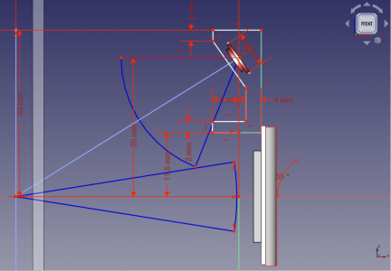
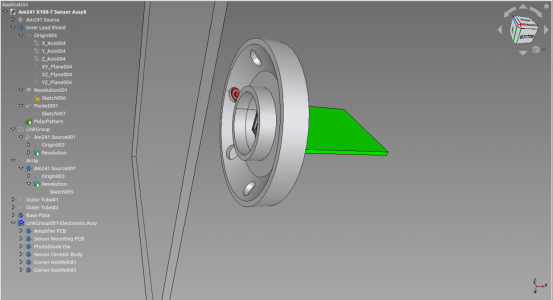
My original geometry sketch
We seem to think alike. Mine was on FreeCAD, trying for the best illumination arcs. This attempt turns out not to be the best. My shield ring around the diode could be set further back. The position of the source pushed into it's shield hole should put the source right near the entry, spraying photons over about 170°. The pale blue normal misleads somewhat. There will be X-rays coming from the entire left side. The missing dimension out of view up top is 1.575 inches. Compared to yours, this one is relatively "roomy". Given your direct experience detecting pulses, I think I have to revise to come in closer for a more "concentrated" approach.

Gamma Illumination & XRF Optics.png .

XRF Mount with AM241 Source2.png

We both have the same basic scheme, except yours goes to almost put the source right up against the sample. I think it's better. We are just going to have to solve whatever it takes to shape some lead. ??
 
Various good suggestions have been made.
We can consider making it of copper, with pockets filled with lead for the sources, then drilled.
Copper delivers a feeble 277eV, below the diode capability.
The shielding only needs to be around the Am241 sources, a piece behind the diode, and a ring around the aperture to the front of the diode.

Various other comments about casting it also.
One option is 3D printing it, and then adding little lead plugs in the right places.

Aluminium is only just about detectable at 1.48keV, and 1.56keVwith 1% probability of absorption, but if it only provides pockets for carefully placed shielding bits, then it can be arranged that the structure contributes zero photons from aluminium structure. For aluminium in the test sample, or aluminum alloy being tested, a count of 10 out of 1000 might be OK.

Dare we try for magnesium? That's 1.25keV and 1.3keV. Probability of absorption about 0.5%
I am still thinking this one through. I kind of wish the detector was just a teensy bit better for low energy photons.
 
Back
Top