- Joined
- Dec 3, 2023
- Messages
- 81
Hi all,
I bought this lathe this summer to do some turning down and threading for a project. It was aluminum material, so I got it done, but the quality could have been better. So after doing multiple turning and threading operations, I was finding the limitations of the machine and it's operator... as follows:
I thought the compound was pulsing ever so slightly, so I tightened the Gibs carefully. I made some more cuts and shortened up my tool as much as I could and it seemed better. A day or two later, my compound again seemed to be loose, which I had trouble understanding since the gib screws had not moved. I took it apart and found plastic gibs, and did some research on them. Honestly, I can't see how these could even be a choice for Gib material but there they are. I've purchased a pair of steel gibs made for this machine. I was wondering if there are any problems with using them and what kind of improvement in performance I could expect.
The other thing I don't like is that there is no reverse on the lathe and I see the benefit of threading away from the headstock with an upside down cutter, but I have 2 potential problems.
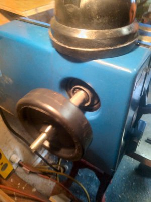
1) The motor is reversible, but the 4 pole windings have pairs of wires on 3 poles that have to be split and recombine with different wires on another pole. The Drum switch that I bought have some bonded contact options but there wasn't enough poles on the switch to handle the permutation of changes needed to be made because any two wires that shared a bonded pair of poles in the switch could not be on those same poles to reverse the spin, and if you just removed the bonding arms then they aren't connected for the forward spin. Is there such a thing as a reversible motor that has too many permutations to be used with a switch?? I see all kinds of motors which have much simpler wiring and can easily hook up to a 8 pole drum switch to be reversible, but my current motor while reversible, seems to require a switch with a much larger number of poles to achieve both configurations.... perhaps I'm not seeing the obvious, so I figured I'd ask if the motor winding configuration could be one that doesn't lend itself to a switched application yet still be a reversible motor.
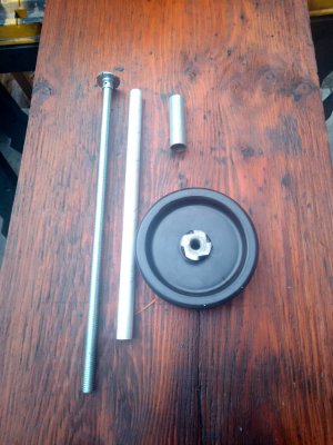
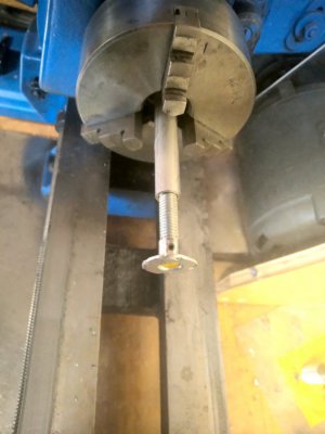
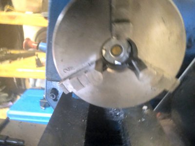
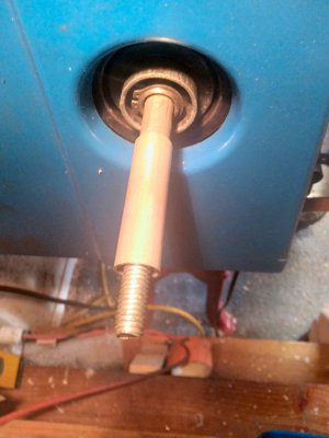
2) I'm also thinking about making a drawbar with reverse threads and a face plate to sit at the bottom of the chuck to keep the screw-on chuck from unscrewing when turning in reverse. I've read both sides of the "unscrewing chuck in reverse" debate online. It doesn't seem like it would be too hard to make a draw bar style retainer for the chuck when turning in reverse. I realize that I would lose the hollow spindle capacity, and that threading operations are probably a pretty slow RPM process too so I might be a little paranoid about crashing into the headstock. I'm just wondering if the draw bar idea has a flaw that I don't yet see?
*I did turn the lathe backwards by hand to keep my cutter aligned with the threads and once I forgot that I disengaged the back gear to back up easier. Then, when I started the next pass, I just about freaked out when the cutter moved out at much higher speed and I just turned the machine off in time for the compound to coast to a stop with the cutter almost beyond the gutter which it had to stop inside of. That close call had me thinking about the video I saw about turning with upside down cutters, away from the headstock...
Thanks in advance for any opinions or suggestions.
I bought this lathe this summer to do some turning down and threading for a project. It was aluminum material, so I got it done, but the quality could have been better. So after doing multiple turning and threading operations, I was finding the limitations of the machine and it's operator... as follows:
I thought the compound was pulsing ever so slightly, so I tightened the Gibs carefully. I made some more cuts and shortened up my tool as much as I could and it seemed better. A day or two later, my compound again seemed to be loose, which I had trouble understanding since the gib screws had not moved. I took it apart and found plastic gibs, and did some research on them. Honestly, I can't see how these could even be a choice for Gib material but there they are. I've purchased a pair of steel gibs made for this machine. I was wondering if there are any problems with using them and what kind of improvement in performance I could expect.
The other thing I don't like is that there is no reverse on the lathe and I see the benefit of threading away from the headstock with an upside down cutter, but I have 2 potential problems.
1) The motor is reversible, but the 4 pole windings have pairs of wires on 3 poles that have to be split and recombine with different wires on another pole. The Drum switch that I bought have some bonded contact options but there wasn't enough poles on the switch to handle the permutation of changes needed to be made because any two wires that shared a bonded pair of poles in the switch could not be on those same poles to reverse the spin, and if you just removed the bonding arms then they aren't connected for the forward spin. Is there such a thing as a reversible motor that has too many permutations to be used with a switch?? I see all kinds of motors which have much simpler wiring and can easily hook up to a 8 pole drum switch to be reversible, but my current motor while reversible, seems to require a switch with a much larger number of poles to achieve both configurations.... perhaps I'm not seeing the obvious, so I figured I'd ask if the motor winding configuration could be one that doesn't lend itself to a switched application yet still be a reversible motor.
2) I'm also thinking about making a drawbar with reverse threads and a face plate to sit at the bottom of the chuck to keep the screw-on chuck from unscrewing when turning in reverse. I've read both sides of the "unscrewing chuck in reverse" debate online. It doesn't seem like it would be too hard to make a draw bar style retainer for the chuck when turning in reverse. I realize that I would lose the hollow spindle capacity, and that threading operations are probably a pretty slow RPM process too so I might be a little paranoid about crashing into the headstock. I'm just wondering if the draw bar idea has a flaw that I don't yet see?
*I did turn the lathe backwards by hand to keep my cutter aligned with the threads and once I forgot that I disengaged the back gear to back up easier. Then, when I started the next pass, I just about freaked out when the cutter moved out at much higher speed and I just turned the machine off in time for the compound to coast to a stop with the cutter almost beyond the gutter which it had to stop inside of. That close call had me thinking about the video I saw about turning with upside down cutters, away from the headstock...
Thanks in advance for any opinions or suggestions.