- Joined
- Jan 20, 2016
- Messages
- 602
I think I figured out how I can make some way covers for between the saddle and column. I want something that would keep chips and coolant off of the ways and ballscrew, without collecting chips until it jams everything up. The stock set up with the thick rubber sheet worked ok, but it collected chips, and kept getting bunched up so that any time I worked on something larger than 3" wide, the vise would rub against the cover until it ripped. The according style covers seemed ok, except that they caught chips like crazy and were difficult to keep clean. The ones on the Z axis also ended up tearing after the vise rubbing it too many times.
What I really want is some of those sheet metal telescoping ways that you see on the real VMCs. They seem to protect well, easy to brush off the chips that gather on them, and last a long time. The problems is that bending and welding sheet metal covers like that so they slide well while not having excessive clearance requires skill and equipment beyond my capabilities. I tried to come up with something that I can reasonably make that will work well. Since I am a lot better at machining than bending and welding, I tried to stick to machining as much as I could.
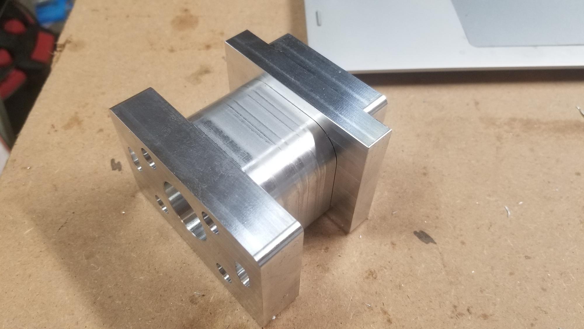
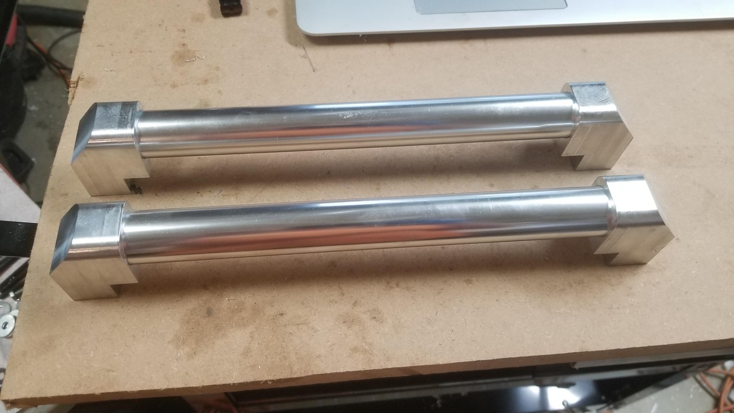
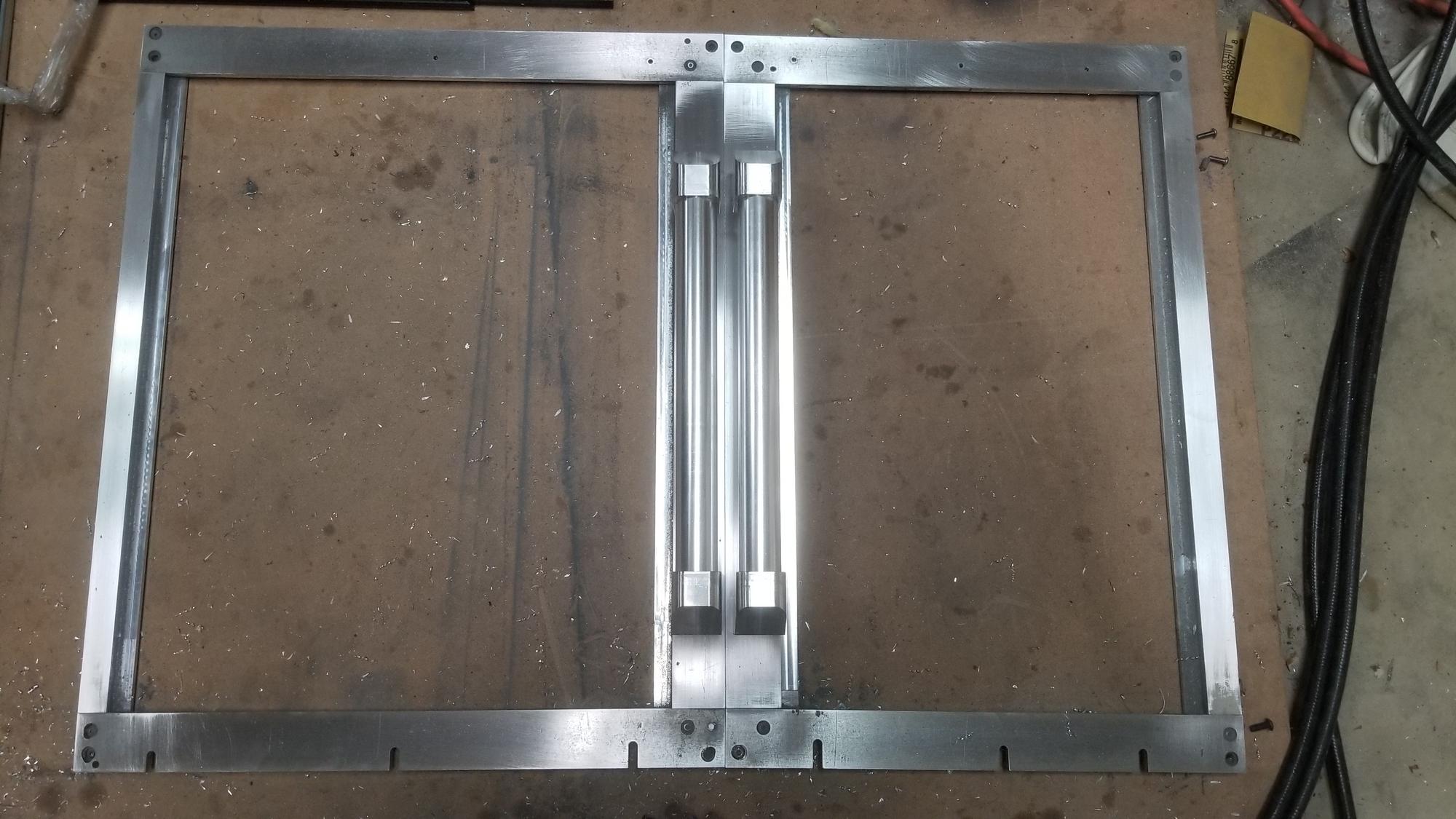
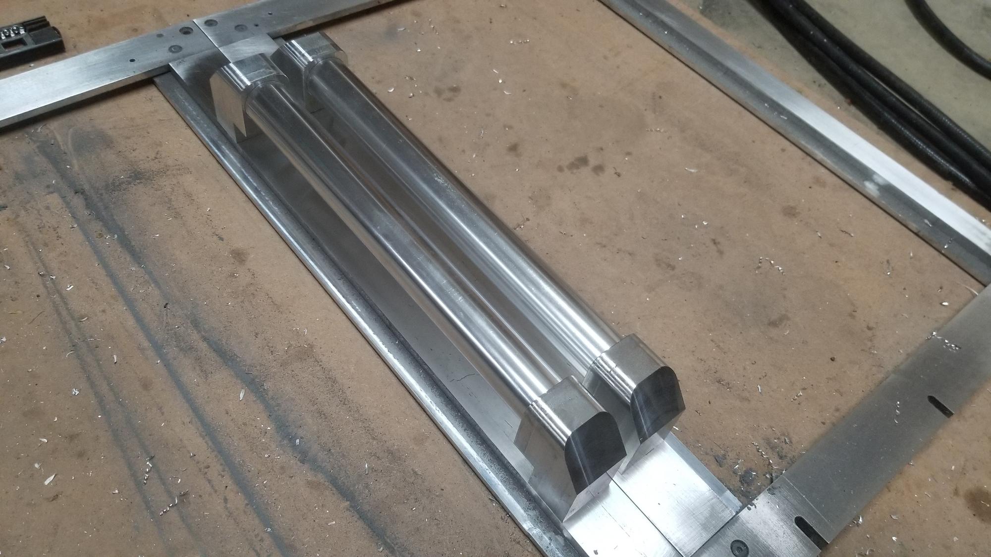
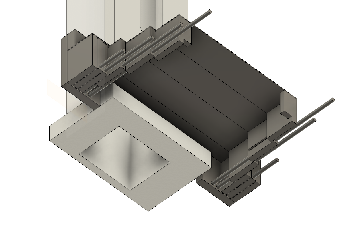
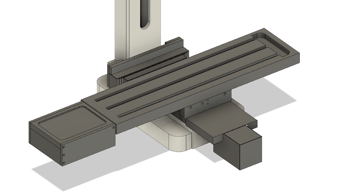
What I came up with is basically aluminum blocks that slide on rails with a piece of sheet metal attached to the top. This way I can closely control the clearance between the parts and control their movement. The blocks will have little pins sticking out of them that will ride in the a slot of the adjacent block. This way, when the first segment reaches the end of its length, the pin will reach the end of the slot and start pulling the next one. Then when that one reaches the end, it starts pulling the next one. When they go the other direction, the table will push the first all the way back in, then the second, the third, etc. I will use either felt or rubber as wipers for the covers to keep chips from getting under them between the spaces. The two end segments will be fixed to the saddle and the column. I am planning to use "tight tolerance stainless round bar" from mcmaster for the rails.
Here is a picture of the top.
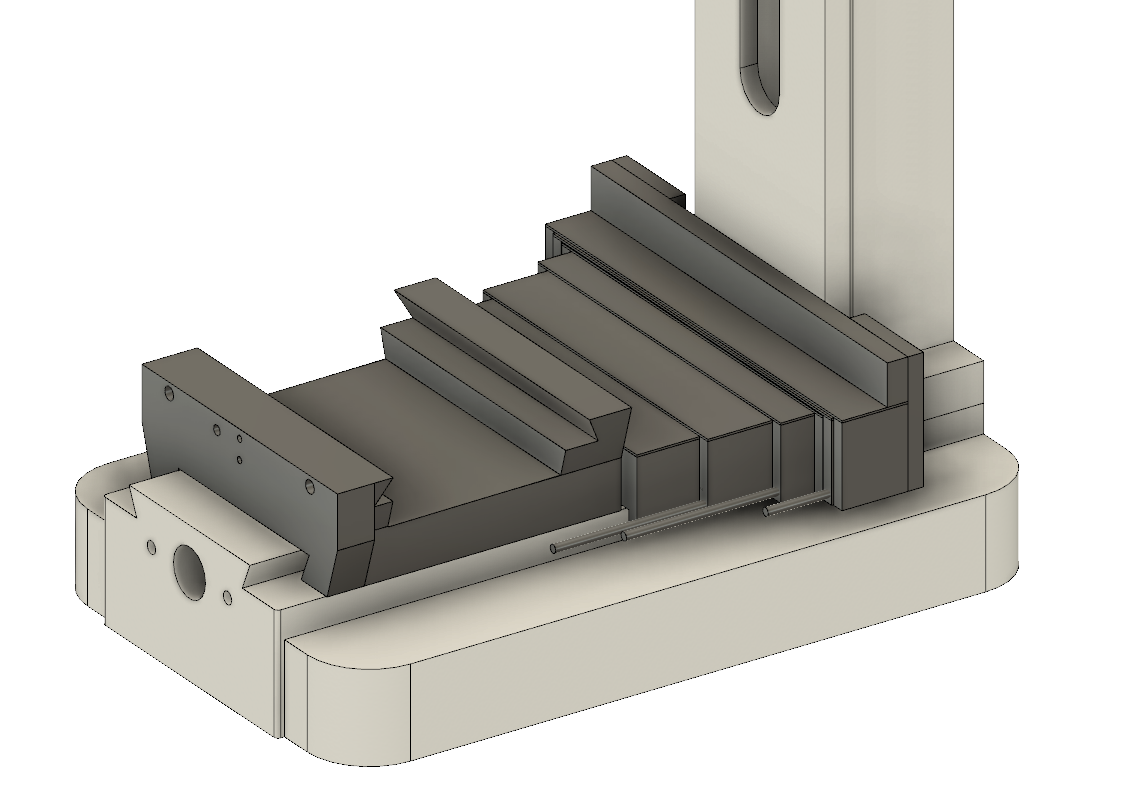
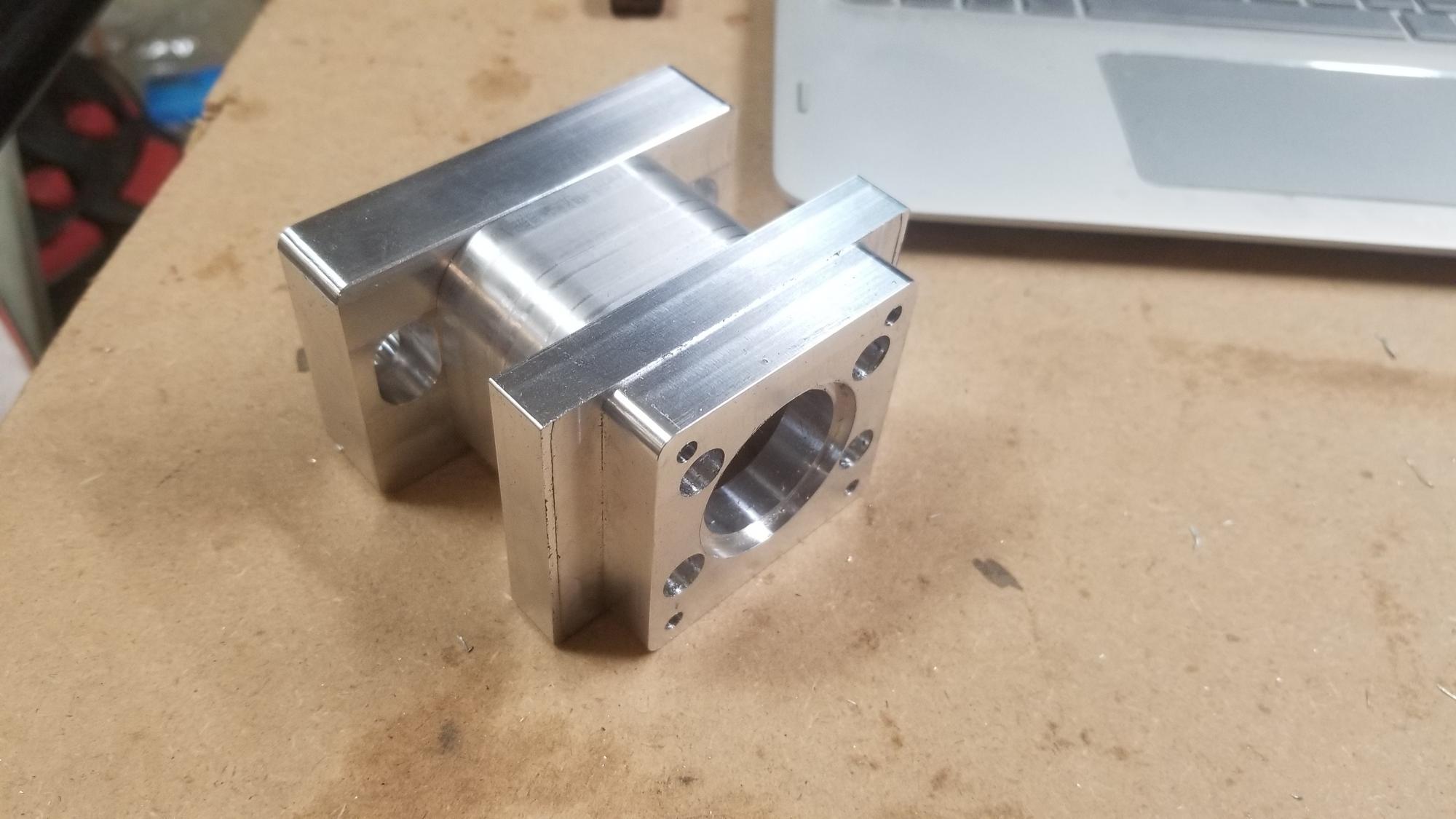
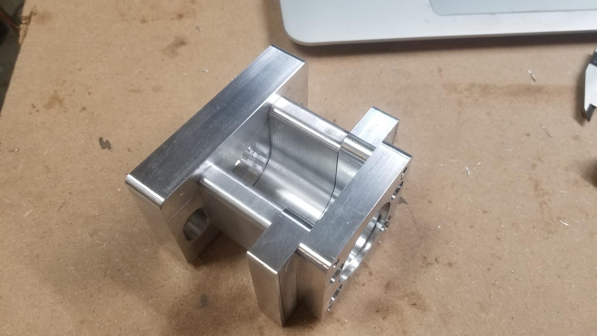
Here is a picture of the bottom.
I have also designed the covers for the X and Y axis motors. The X looks very similar to the way Tormach covers their motor. Its just a box that surrounds the motor to keep chips and coolant off of it. The Y axis has a sheet metal box that mounts to the motor mount specifically to protect the motor, then a moving section attaches to the saddle that will protect the ways when the saddle is moved toward the column.
Any thoughts, feedback or suggestions are welcomed and appreciated!
What I really want is some of those sheet metal telescoping ways that you see on the real VMCs. They seem to protect well, easy to brush off the chips that gather on them, and last a long time. The problems is that bending and welding sheet metal covers like that so they slide well while not having excessive clearance requires skill and equipment beyond my capabilities. I tried to come up with something that I can reasonably make that will work well. Since I am a lot better at machining than bending and welding, I tried to stick to machining as much as I could.
What I came up with is basically aluminum blocks that slide on rails with a piece of sheet metal attached to the top. This way I can closely control the clearance between the parts and control their movement. The blocks will have little pins sticking out of them that will ride in the a slot of the adjacent block. This way, when the first segment reaches the end of its length, the pin will reach the end of the slot and start pulling the next one. Then when that one reaches the end, it starts pulling the next one. When they go the other direction, the table will push the first all the way back in, then the second, the third, etc. I will use either felt or rubber as wipers for the covers to keep chips from getting under them between the spaces. The two end segments will be fixed to the saddle and the column. I am planning to use "tight tolerance stainless round bar" from mcmaster for the rails.
Here is a picture of the top.
Here is a picture of the bottom.
I have also designed the covers for the X and Y axis motors. The X looks very similar to the way Tormach covers their motor. Its just a box that surrounds the motor to keep chips and coolant off of it. The Y axis has a sheet metal box that mounts to the motor mount specifically to protect the motor, then a moving section attaches to the saddle that will protect the ways when the saddle is moved toward the column.
Any thoughts, feedback or suggestions are welcomed and appreciated!