-
Welcome back Guest! Did you know you can mentor other members here at H-M? If not, please check out our Relaunch of Hobby Machinist Mentoring Program!
You are using an out of date browser. It may not display this or other websites correctly.
You should upgrade or use an alternative browser.
You should upgrade or use an alternative browser.
New project, I'm in over my head.....
- Thread starter bpimm
- Start date
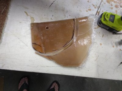
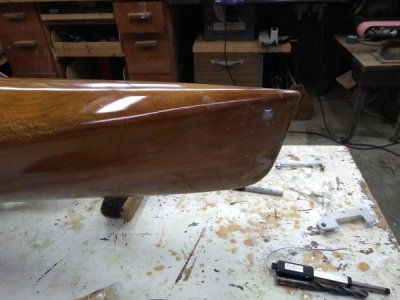
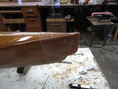
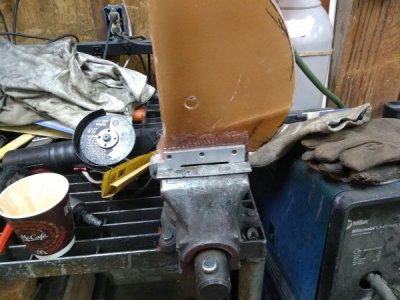
Tonight I beded in the bracket to the cast. I'll. Drill it and bolt it in case the epoxy ever let's go.
Today we wired it all up, my brother has been working on the controls, and tested it out. Wow this thing pushes water. It could be a rather fast kayak, we'll see this weekend.
Once the bracket cure's I can work on the final assembly and making the last few parts.

Today we wired it all up, my brother has been working on the controls, and tested it out. Wow this thing pushes water. It could be a rather fast kayak, we'll see this weekend.
Once the bracket cure's I can work on the final assembly and making the last few parts.
- Joined
- May 16, 2016
- Messages
- 1,698
Definitely not in over your head, that is an excellent project and very well done.
F
Firestopper
Forum Guest
Register Today
Excellent work and well within your skillset. Where did you source the aero tube?
Excellent work and well within your skillset. Where did you source the aero tube?
Thanks, my skillset is much broader after this project...
The aero tube came from Wicks aircraft and motorsports.
A little bad news today, I was working on one of the brackets to hold the steering servo and the computer driving the CNC Mill decided it had reached end of life in the middle of the part. Woludn't reboot. I tried it's HD in the computer that drives my cnc plasma but it wouldn't boot, it got a lot further than in the original PC. All the power supplies are there so it looks bad.
I'm going to make a part to lock the steering strait so we can test the motor, just will have to run strait and turn with the paddle.
Damn computers anyway.
I'm going to make a part to lock the steering strait so we can test the motor, just will have to run strait and turn with the paddle.
Damn computers anyway.
Had a great weekend on the water and got some testing done on the motor, Way more power than we need and a better motor controller is in the plans. the minimum stable turn on speed is 4 MPH, once you're moving you can slow it down a little more but it's a little unstable. My brother has found a controller that should do the trick. At full power we think it limited to hull speed at 6.2 MPH.
Here are some VIDEOS that my son shot.
The first one is powering away from the dock at minimum turn on speed followed by a full power pass.
The second one is a full power pass with some fake paddling for the crowd on the dock..
Third is when I was manually adjusting the speed down for a running minimum.
fourth is just another pass.
Overall it was a success, we have more work to do, like fix my cnc and get the steering and lift installed, also going to look at shortening the length, I arbitrarily chose 4" of water over the prop to combat cavitation but it drives the back of the Kayak down when you're under power so I don't think it needs to be so deep.
We're using a pair of 5.0 AH hobby lithium packs similar to These. Discharge time is totally dependent on speed at the slowest cruise I got it down to probably 2-3 hours, full speed who knows. When we tested it in the hot tub, pushing against the side, the slowest start up witch gave us 4 MPH cruise which is still pretty fast it was drawing 7 Amps IIRC, at full speed which got us to 6.2 MPH it was drawing 45 Amps. So if we can get it slower it will last longer, if I remember my calcs right a 5 amp draw would go 2 hours, and if we could get it down to a 1 Amp draw it would go 10 hours.
Once the new controller is online we can do some more testing for the battery life, can always add more batteries as well, they're less than a pound each.
It was fun testing, I can't wait to try it with steering. We even came in second in class with 1 boat in the sailboat class, lost to a local by 2 votes with a beautiful boat that won best in show last year, and we ended up finding it a new home with someone that will enjoy it and take care of it. Dad's been thinking of selling it for several years because we just don't use it, and a local guy fell in love with it, good for everyone.
Finally got the mill back up and running, had to spring for a smooth stepper as the new old computer we put together out of spare parts wouldn't work.
Now the part I was making when it died is done.
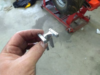
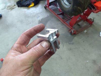
This part mounts to the lift bracket and the servo mounts to it.
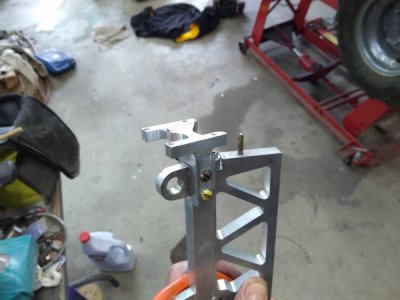
Then the servo,
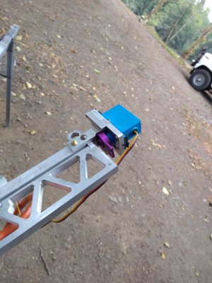
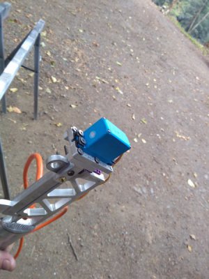
all together.
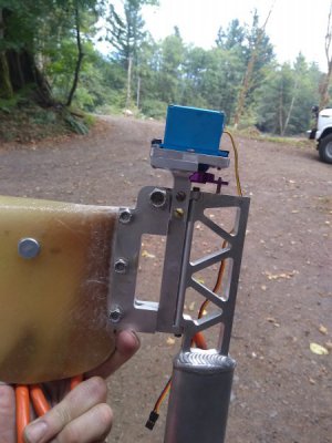
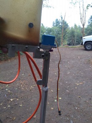
Now it's on to making the lift mechanism. And getting some proper hardware...
Now the part I was making when it died is done.


This part mounts to the lift bracket and the servo mounts to it.

Then the servo,


all together.


Now it's on to making the lift mechanism. And getting some proper hardware...


